The Simple Subnetting Guide
Subnetting is the first major hurdle which trips up many aspiring network professionals. There are plenty of guides on the internet for how to subnet, but these rarely explain the “why” of subnetting and often overcomplicate the method, which leaves students confused and frustrated.
This guide takes a different approach. We’ll explain everything end-to-end, including our tricks for fast and easy subnetting, practical examples of real-life subnetting scenarios, and routing concepts which are key to putting your new skills to use.
IP Addresses
IP addresses are typically displayed as numerical values in dotted decimal notation, such as this one, which may be familiar to you:
192.168.1.1
The numbers that you see in an IP address are actually representations of binary. Each dot in the IP address separates 8-bit sections called octets. Below is the above IP address represented in binary:
11000000.10101000.00000001.00000001
But how did we figure out the binary? The answer is that each of the 8-bits in an octet have an assigned value when they are set to 1. These values are added together, which produces the whole numbers seen in the IP address:
1    1    1    1    1    1    1    1
128  64   32   16   8    4    2    1

128 + 64 + 32 + 16 + 8 + 4 + 2 + 1 = 255
As you can see, when all of the bits are set to 1, the octet has a value of 255. When bits in an octet are set to 0, their assigned value is not added to the total. Looking at the first octet of 192.168.1.1 demonstrates this clearly:
1    1    0    0    0    0    0    0
128  64   32   16   8    4    2    1

128 + 64 + 0 + 0 + 0 + 0 + 0 + 0 = 192
The next octet is a bit trickier, but still straightforward to figure out:
1    0    1    0    1    0    0    0
128  64   32   16   8    4    2    1

128 + 0 + 32 + 0 + 8 + 0 + 0 + 0 = 168
The final two octets both have a value of 1, so they are both calculated like this:
0    0    0    0    0    0    0    1
128  64   32   16   8    4    2    1

0 + 0 + 0 + 0 + 0 + 0 + 0 + 1 = 1
Binary Practice
On your own with a sheet of paper, try to convert these four binary octets into a human-readable IP address:
10101100.00010000.01000001.00000101
Now convert the following IP address to binary:
10.255.99.36
IP Address Ranges
Since IP addresses are used by devices to communicate, it makes sense to group them together in logical ways. Your home WiFi router likely has an IP address similar to 192.168.1.1, which is a common default setting for consumer routers. Whenever you’re connected to your home WiFi, your device is likely to get an IP address which appears largely similar to you router’s IP address. Your home network might end up looking like this:
192.168.1.1   - Router
192.168.1.2   - Printer
192.168.1.3   - PS5
192.168.1.4   - Laptop
...
etc.
Based on what you now know about binary octets, you might have realized already that the possible range of the last octet is 0 to 255. Essentially, you have a block of IP addresses which can be represented as 192.168.1.X, where X is a number belonging to some host on your network.
For the sake of our example, the first three octets are always the same, therefore they represent the network. The value in the final octet, however, is variable based on the host in the network. The difference between a network (a group of IPs) and a host (an IP within the group) is central to understanding subnetting.
Unfortunately, an IP address alone tells us nothing about the true scope of a network. In reality, the size of this range depends entirely on the subnet mask — not on how the numbers look at first glance. In order to take this from hypothetical grouping of IP addresses to actionable, logical use-cases, we need to delve into subnet masks and their role in determining the size of the network and host sections of an IP address range.
Subnet Masks
Subnet masks are similar to IP addresses in their makeup — four 8-bit octets expressed in dotted decimal notation — but their purpose is different. Specifically, they exist to inform our routers and other devices about the IP address range of a network. Consider the following subnet mask:
255.255.255.0
Breaking that down into binary:
11111111.11111111.11111111.00000000
Subnet masks use the binary 1 to designate network bits of the subnet mask. The binary 0 is used to designate host bits. Let’s look at our example network again, but with a proper subnet mask:
192.168.1.0 255.255.255.0
We can learn quite a lot about this device’s subnet by examining the subnet mask in binary, then counting the number of network bits and host bits:
11111111.11111111.11111111.00000000
|------------------------| |------|
     24 network bits       8 host bits
Here we can see that 24 bits are reserved for the network portion of the subnet mask, and 8 bits are reserved for the host portion. We will go into each of these, starting with the host bits.
Understanding Host Bits
To find the number of usable IP addresses in a given subnet, count the number of host bits (0s) in the subnet mask and plug that number into this equation as x:
2x - 2 = Number of usable IPs
Our subnet mask has 8 host bits, so:
28 - 2 = 256 - 2
= 254 usable IPs
In each subnet there are two special IPs which are reserved and cannot be assigned to hosts. The first is the network address, which is the first possible IP address in the subnet (192.168.1.0 in our case). The second is the broadcast address, which is the last possible IP address in the subnet (192.168.1.255). This is why we subtract 2 from the total.
Naturally, more host bits in the subnet mask allows for larger and larger pools of IP addresses at the expense of network bits. For example:
Network ID : 192.168.1.0 255.255.240.0
Binary Mask: 11111111.11111111.11110000.00000000
This subnet mask has 12 host bits instead of 8. Let’s plug that into the equation:
212 - 2 = 4096 - 2
= 4094 usable IPs
That’s a lot of IP addresses! On the surface, this may seem confusing — why bother learning to subnet if we can just throw everything into one big network? The answer is that every subnet is a broadcast domain. Hosts routinely use broadcasts for things such as ARP and DHCP, and when this happens, every other host on the network receives the broadcast. This is an inefficient use of bandwidth on the network and processing power on the devices, and it opens up a world of hurt when something like Spanning Tree Protocol goes awry on a broadcast domain that large.
The better solution is to take this large chunks of IP addresses and create subnetworks (subnets) out of it. That way, we can support the same number of IP addresses while mitigating the impact of problems that occur within a single broadcast domain. This is where network bits in the subnet mask become relevant.
Understanding Network Bits
When it comes to subnetting, the subnet mask holds a critical piece of information in its network bits:
11111111.11111111.11111111.00000000
                         ^
                    Final network bit (Value = 1)
The final network bit of a subnet mask is important for two reasons:
The octet which contains the final network bit is called the interesting octet.
The value of the final network bit is called the magic number and determines how networks are subnetted. (This will make more sense soon.)
In our case, the final network bit has a value of 1, and it’s in the third octet. This means that if we want to add more subnets of the same size to our network, we increment the third octet by 1:
192.168.1.0 255.255.255.0
192.168.2.0 255.255.255.0
192.168.3.0 255.255.255.0
... etc.
Here’s are some new networks and subnet masks to help illustrate the point:
# The third octet is the interesting octet, and the
# value of the final network bit is 64. Therefore
# the third octet increments by 64. Each block is
# a new subnet.

Network A   :  10.0.0.0 255.255.192.0
Binary Mask :  11111111.11111111.11000000.00000000
                                  ^
                           Final network bit (Value = 64)

Network B   : 10.0.64.0  255.255.192.0
Network C   : 10.0.128.0 255.255.192.0
Network D   : 10.0.192.0 255.255.192.0

----------------------------------------------------

# The fourth octet is the interesting octet, and the
# value of the final network bit is 4. Therefore
# the fourth octet increments by 4. Each block is
# a new subnet.

Network A   : 172.16.1.0 255.255.255.252
Binary Mask : 11111111.11111111.11111111.11111100
                                              ^
                                          Value = 4
Network B   : 172.16.1.4 255.255.255.252
Network C   : 172.16.1.8 255.255.255.252
Network D   : 172.16.1.12 255.255.255.252
Understanding the role of the final network bit (“magic number”) is key to understanding subnetting. Once you’ve memorized the values of each binary position in an octet, you will likely be able to subnet quickly and accurately in your head.
A Quick Note on CIDR Notation
Classless Interdomain Routing (CIDR) is a fancy term which describes the system of variable-length subnet masks which you have learned in this guide. Up until this point, you’ve seen subnet masks expressed in dotted-decimal notation, e.g. 255.255.255.0. But there is another, faster way to express subnet masks through the use of CIDR notation — which is a slash followed by the number of network bits in the subnet mask:
DDN:  192.168.1.0 255.255.255.0
CIDR: 192.168.1.0/24

DDN:  172.16.20.16 255.255.255.252
CIDR: 172.16.20.16/30
The combination of a network ID and CIDR notation (e.g. 192.168.1.0/24) forms what is called a CIDR prefix or simply a prefix. From now on, we will use CIDR prefixes in our examples for ease of reading.
Subnetting Examples
Putting together what we know about host bits and network bits, we can plan out our networks in a logical manner based on specific needs. To help provide some context for what you have learned so far, let’s dive into a hypothetical scenario where a business is standing up a new network.
You’re a junior network engineer, and you’ve been asked to subnet a block
of IP space which has been reserved for a new campus network. Below is a
list of the networks which need to be supported, as well as the number of
devices expected in each network:

Wired    - 1300 devices
Wireless - 400 devices
Voice    - 1300 devices
Guest    - 400 devices

A senior engineer has allocated the following IP block to use for this site:

10.16.16.0/20
Is this address space large enough to accommodate all of our devices? Let’s see how many host IPs this network can support in total:
CIDR:   /20
DDN:    255.255.240.0
Binary: 11111111.11111111.11110000.00000000
                              |-----------|
                               12 host bits

Devices:  1300 + 1300 + 400 + 400 = 3,400
Host IPs: 2^12 - 2 = 4094
Yes! We have enough IP space to support all of our devices. The challenge is to allocate them into appropriately-sized subnets. To see how we might be able to do that, let’s figure out a few key pieces of information:
What is the first available IP address in 10.16.16.0/20?
What is the last available IP address in 10.16.16.0/20?
What is the broadcast address?
What is the total range of IP addresses?
Finding the first IP address in the range is easy. It’s always one spot above the network address:
Network ID: 10.16.16.0/20
First IP:   10.16.16.1
The last IP requires knowledge of the network bits of a subnet mask, and the magic number concept we discussed earlier:
Our Network:  10.16.16.0/20
Binary Mask: 11111111.11111111.11110000.00000000
                                  ^
                              Value = 16
# Third octet is interesting.
# Final network bit value = 16

Next Network: 10.16.32.0/20
We can find the range of our network by examining the network bits in the subnet mask. We know that the next available /20 network begins at 10.16.32.0, therefore we can deduce the broadcast address and last available host IP in our range:
Network ID: 10.16.16.0/20
First IP:   10.16.16.1
Last  IP:   10.16.31.254
Broadcast:  10.16.31.255
In case you’re confused how we got here, keep in mind that incrementing IP addresses past bit boundaries looks like this:
10.16.16.1
...
10.16.16.254
10.16.16.255
10.16.17.1
10.16.17.2
...
10.16.17.255
10.16.18.1
etc.
So now we know that our range of IPs for our network is 10.16.16.1 to 10.16.31.254. The next step is to figure out how to fit our four subnets into this network. In other words, we’re going to split up our /20 into subnets which are large enough to accommodate our hosts. Again, the device totals are as follows:
Wired    - 1300 devices
Wireless - 400 devices
Voice    - 1300 devices
Guest    - 400 devices
Let’s focus on the wired and voice subnets first, since they are the largest. Each address range that we carve out of 10.16.16.0/20 for these subnets should be large enough to accommodate 1300 IPs, with a bit of room for growth if possible.
To figure out how many host bits we need in the subnet mask for this network, we can just do some quick math:
2^1  - 2 = 0     <-- We'll talk about this later...
2^2  - 2 = 2
2^3  - 2 = 6
2^4  - 2 = 14
2^5  - 2 = 30
2^6  - 2 = 62
2^7  - 2 = 126
2^8  - 2 = 254
2^9  - 2 = 510
2^10 - 2 = 1,022
2^11 - 2 = 2,046 <-- Uh oh...
You might be able to see already that we have a problem. In order to accommodate our wired and voice subnets, we would have to give them both way more host IPs than they need. And worse, there is no IP space left for our other subnets once we assign them!
32 bits - 11 host bits = 21 network bits

10.16.16.0/21 - Wired (2046 IPs)
10.16.24.0/21 - Voice (2046 IPs)

= 4092 IPs

No room left in the /20! :(
We have a couple of options in this scenario. We can simply use a larger range for our site, or we can use our space more efficiently. Expanding the subnet is easy enough. Let’s use the network 10.16.0.0/19 instead:
Network ID:  10.16.0.0/19
Binary Mask: 11111111.11111111.11100000.00000000
                                 ^
                              Value = 32

Host IPs:   2^13 - 2 = 8,190
First IP:   10.16.0.1
Last  IP:   10.16.31.254
Broadcast:  10.16.31.255
Next Net:   10.16.32.0/19
Now we can easily fit our subnets, albeit with a lot of wasted IP space:
10.16.0.0/21  - Wired     (2046 IPs)
10.10.8.0/21  - Voice     (2046 IPs)
10.10.16.0/21 - Wireless  (2046 IPs)
10.10.24.0/21 - Guest     (2046 IPs)
This approach is tempting, but it is an inefficient use of address space. We only have 3400 devices, but we’ve dedicated over 8000 host addresses to this site. Moreover, our wireless and guest subnets have way more IPs than they actually need. Wasting address space is considered bad practice, and it often comes back to bite you!
Instead, let’s say that we’re stuck with our measly 10.16.16.0/20 subnet to work with. The senior engineer isn’t going to waste a /19’s worth of address space on this site. Is there a way we can fit all of our devices into this /20 while keeping them in separate subnets?
Imagine our the new site has three floors, and devices are spread out across them relatively equally. With this in mind, we don’t necessarily need to give every PC or phone an address on the same subnet — we can split up the subnets per floor in order to use our address space more efficiently.
10.16.16.0/23 = Wired1 (Floor 1, 510 IPs)
10.16.18.0/23 = Wired2 (Floor 2, 510 IPs)
10.16.20.0/23 = Wired3 (Floor 3, 510 IPs)

= 1530 IPs

10.16.22.0/23 = Voice1 (Floor 1, 510 IPs)
10.16.24.0/23 = Voice2 (Floor 2, 510 IPs)
10.16.26.0/23 = Voice3 (Floor 3, 510 IPs)

= 1530 IPs
This is much more reasonable. Just by splitting up our address space in a logical manner, we saved over 1000 host IPs which would have sat unused. We can split the remaining address space between our Guest and Wireless networks with plenty of room to spare:
10.16.28.0/23 = Wireless (510 IPs)
10.16.30.0/23 = Guest    (510 IPs)
This example leaves us with the following subnet ranges, which fit neatly together into our /20 network:
10.16.16.0/23 - Wired1, Floor1 (510 IPs)
10.16.18.0/23 - Wired2, Floor2 (510 IPs)
10.16.20.0/23 - Wired3, Floor3 (510 IPs)
10.16.22.0/23 - Voice1, Floor1 (510 IPs)
10.16.24.0/23 - Voice2, Floor2 (510 IPs)
10.16.26.0/23 - Voice3, Floor3 (510 IPs)
10.16.28.0/23 - Wireless       (510 IPs)
10.16.30.0/23 - Guest          (510 IPs)

= 4080 IPs
Keep in mind that this is just one example of how subnetting can be used. The rules for scoping and organizing subnets are fairly rigid, but there is a surprising amount of flexibility when it comes to planning them out. Most network teams have established practices or patterns for subnetting which may be different than what you’re used to doing in a lab or at your own workplace. This is why it’s important to have a good understanding of the fundamentals — you’ll always be prepared when confronted with different subnetting scenarios.
Point-to-Point Subnets
Networks are full of point-to-point links between routers. By definition, only two devices sit on a point-to-point link, so only two useable IP addresses are needed - one for each interface on either end of the connection. Two prefix lengths, the /30 and /31, are typically used for this purpose.
The /30 Prefix
This is the most common subnet assigned to point-to-point subnets. After subtracting IPs for the network and broadcast addresses, we’re left with exactly two usable host IP addresses to use for the subnet:
CIDR:        10.0.0.0/30
DDN:         255.255.255.252
Binary Mask: 11111111.11111111.11111111.11111100
                                             ^
                                         Value = 4

Host IPs:    2^2 - 2 = 2
Network:     10.0.0.0
First IP:    10.0.0.1
Last  IP:    10.0.0.2
Broadcast:   10.0.0.3
Next Net:    10.0.0.4/30
One end of this connection would be configured with an IP/mask of 10.0.0.1/30 and the other would have 10.0.0.2/30. The most common method to handle this at scale is to designate an address range for point-to-point links, then dedicate /30 subnets for each connection:
P2P Subnet: 10.0.0.0/24

RouterA <-> RouterB: 10.0.0.0/30
RouterA <-> RouterC: 10.0.0.4/30
RouterA <-> RouterD: 10.0.0.8/30
...
...
RouterY <-> RouterZ: 10.0.0.252/30
For this example, when we run out of room in our /24, we can either expand the subnet or simply find a new /24 to use for our additional /30s. Keep in mind that the /23 subnet below actually contains the same address space as both /24 subnets:
Expanded P2P Subnet: 10.0.0.0/23

OR

P2P Subnet 1: 10.0.0.0/24
P2P Subnet 2: 10.0.1.0/24

RouterA <-> RouterB: 10.0.0.0/30
RouterA <-> RouterC: 10.0.0.4/30
RouterA <-> RouterD: 10.0.0.8/30
...
...
RouterY <-> RouterZ: 10.0.0.252/30
RouterY <-> RouterX: 10.0.1.0/30
RouterY <-> RouterW: 10.0.1.4/30
RouterY <-> RouterV: 10.0.1.8/30
...
...
RouterA <-> RouterZ: 10.0.1.252/30
The /31 Prefix
While the /30 is the most common approach to point-to-point subnets, there is also the often-misunderstood and seldom-used /31 subnet, in which there are evidently zero IP addresses in the usable host range:
CIDR: /31
DDN:  255.255.255.254
Binary Mask: 11111111.11111111.11111111.11111110
                                              ^
                                          Value = 2
Hosts: 2^1 - 2 = 0?
On the surface, this does not make sense. How do we use a subnet with zero host IPs? The truth is that /31 behave differently than most other prefixes:
/31 prefixes do not have a broadcast address
/31 prefixes allow a host to use the network address
So in other words, when we calculate the number of useable hosts on a /31 subnet, we do not subtract the two IP addresses which would normally be reserved for the network and broadcast addresses:
CIDR:     10.0.0.0/31
DDN:      255.255.255.254

Network:  10.0.0.0
First IP: 10.0.0.0
Last  IP: 10.0.0.1
Broadcast: N/A

Next Net: 10.0.0.2/31
Some manufacturers may issue warnings in the CLI if you use a /31 subnet, but over the years we have found no reason not to use them. They use half the address space of /30 subnets with no evident downsides. The same network we dedicated for our point-to-point subnets would look like this if broken down into /31s:
P2P Subnet: 10.0.0.0/24

RouterA <-> RouterB: 10.0.0.0/31
RouterA <-> RouterC: 10.0.0.2/31
RouterA <-> RouterD: 10.0.0.4/31
...
etc.
The /32 Prefix
The /32 prefix is often known as the host prefix or host address. It refers to a single IP address, e.g. 172.16.233.55/32.
These prefixes are typically used for loopback addresses or other interfaces associated with a router ID. Other use-cases involve anycast routing, in which multiple routers can advertise the same /32 host address from different locations in a network. A route for a /32 prefix is also known as a host route.
For practical reasons and to avoid unintended overlap, host addresses are often pulled from a pool similarly to P2P subnets. Keeping track of host prefixes is especially important in OSPF or BGP environments, which require each router to have a unique Router ID. It’s easy to manage this by giving each router a unique /32 Router ID from a designated pool:
Designated Host Subnet: 172.16.233.0/24

Host1: 172.16.233.1/32
Host2: 172.16.233.2/32
Host3: 172.16.233.3/32
...
etc.
Routing Between Subnets
Subnetting and routing are two topics which are inextricably linked. It’s difficult to understand one without understanding the other, which makes the situation something of a catch-22 for new learners. For this reason, we’re going to introduce some basic routing concepts here so that you’re able to make sense of the information you’ve learned so far.
Consider the following network:
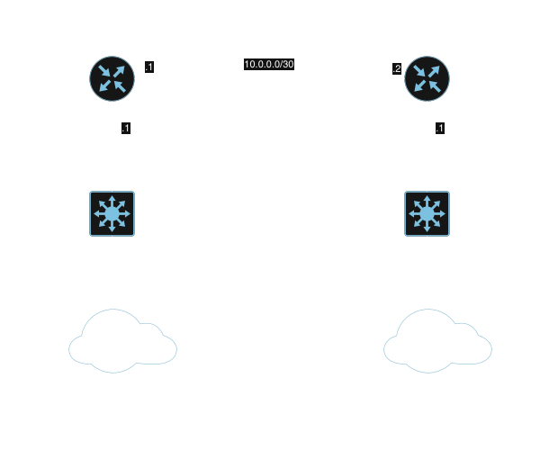
Router A is connected to subnet 192.168.1.0/24 and has an IP address of 192.168.1.1.
Router B is connected to subnet 192.168.2.0/24 and has an IP address of 192.168.2.1.
Router A and Router B are connected over a point-to-point link on subnet 10.0.0.0/30. Router A has 10.0.0.1 and Router B has 10.0.0.2.
For all intents and purposes, subnets are independent broadcast domains. The only way for our LAN subnets to talk to each other is if their traffic is routed by Router A and Router B. Each router has a routing table which it consults to determine the next hop for any particular destination network.
In our simple network, Router A has knowledge of 192.168.1.0/24 and 10.0.0.0/30 because it is directly connected to those networks. It can use ARP to discover hosts within either broadcast domain. Likewise, Router B has knowledge of 192.168.2.0/24 and 10.0.0.0/30.
Neither router, however, has knowledge of the opposite router’s LAN network. The simplest way to fix this is by configuring static routes on Router A and Router B, so that each router knows to send traffic over the point-to-point link when the destination is the distant subnet:
! Static route for Router A
!
RouterA(config)# ip route 192.168.2.0 255.255.255.0 10.0.0.2
!
! Static route for Router B
!
RouterB(config)# ip route 192.168.1.0 255.255.255.0 10.0.0.1
Let’s expand this example to make it a little more relevant to subnetting:
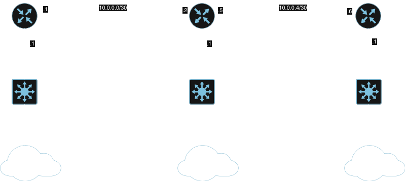
We’ve added an additional router - RouterC - which is attached to its own LAN subnet 172.16.0.0/24. It also shares a point-to-point network with Router B on 10.0.0.4/30. We can teach RouterA and RouterB about this new network by adding a couple of more routes:
! Static route for Router A
!
RouterA(config)# ip route 172.16.0.0 255.255.255.0 10.0.0.2
!
! Static route for Router B
!
RouterB(config)# ip route 172.16.0.0 255.255.255.0 10.0.0.6
RouterC also needs routes for the 192.168.1.0/24 and 192.168.2.0/24 networks. We could simply configure two routes on RouterC like this:
RouterC(config)# ip route 192.168.1.0 255.255.255.0 10.0.0.5
RouterC(config)# ip route 192.168.2.0 255.255.255.0 10.0.0.5
But we know how to subnet now! This matters, because we can summarize these two destination networks into a single route using a bit of what we’ve learned:
RouterC(config)# ip route 192.168.0.0 255.255.252.0 10.0.0.5
This route for 192.168.0.0/22 matches both of the /24s attached to RouterA and RouterB:
CIDR:        192.168.0.0/22
DDN:         255.255.252.0
Binary Mask: 11111111.11111111.11111100.00000000
                                    ^
                                Value = 4

Network:   192.168.0.0
First IP:  192.168.0.1
Last IP:   192.168.3.254
Broadcast: 192.168.3.255
Next Net:  192.168.4.0/22
192.168.1.0/24 and 192.168.2.0/24 both fall within the range of 192.168.0.0/22, so we can create a summary route on RouterC which says, “For any IP in the range of 192.168.0.0/22, use RouterB (10.0.0.5) as the next hop.” Route summarization and filtering based on subnet/prefix is extremely common when using dynamic routing protocols such as BGP.
Let’s assume that a few subnets will be added off of RouterA in the future, and we need RouterB and RouterC to be able to reach them:
RouterA Subnets:
  192.168.64.0/24
  192.168.65.0/24
  192.168.80.0/24
  192.168.90.0/24
How could we summarize these subnets? Let’s work it out:
Range: 192.168.64.0 to 192.168.90.255

# How many network bits do we need to get from
# 64 to 90 in the third octet?

Binary Mask: 11111111.11111111.11100000.00000000
                                 ^
                              Value = 32

# Make sure a /19 is large enough to fit
# all of our /24 subnets

CIDR: 192.168.64.0/19
Network:  192.168.64.0
First IP: 192.168.64.1
Last IP:  192.168.95.254
Broadcast: 192.168.95.255
Next Net: 192.168.96.0/19
The prefix 192.168.64.0/19 contains the address space for all of our new /24 subnets off of RouterA, so we can summarize the route accordingly on RouterB and RouterC:
!
! RouterB
!
RouterB(config)# ip route 192.168.64.0 255.255.224.0 10.0.0.1
!
! RouterC
!
RouterC(config)# ip route 192.168.64.0 255.255.224.0 10.0.0.5
There is much more to routing than what we have shown here — but you can likely tell by this point that subnetting and routing are very closely related topics. Learning how to subnet isn’t just for the sake of learning. It is a vital skill if you want to build a career as a network professional.
Conclusion
Subnetting is a skill which is straightforward to learn with the right instruction. As you’ve read in this guide, simply knowing how the subnet mask is organized with host bits and network bits opens the door. When you know how many devices need to be supported, look to the host bits first in order to scope out your network appropriately. Then, when you want to subdivide these networks for security, design, or organizational reasons, look to the network bits and use the magic number to organize your blocks of IP space.
You learned that subnet masks can be expressed as CIDR prefixes, which represent the number of network bits in the subnet mask. You also learned how routing and subnetting are closely related topics due to concepts like route summarization and route filtering.
For continued learning, we recommend digging into routing behavior — specifically the longest prefix match for route selection, prefix lists, and route maps.
Questions or comments? Feel free to drop a message.