Nvidia VXLAN/EVPN Fabrics
This is a step-by-step technical guide which demonstrates how to implement Nvidia VXLAN/EVPN data center fabrics from scratch using Cumulus Linux, NVUE, and Ansible. The lab we use for this guide is built exactly how we would build a real data center fabric in production. It is an effective and well-supported design which is commonly used in modern data centers all over the world.
We used Nvidia Air as our lab environment, which is free to use after signing up with a business email address. An important note if you intended to follow along: When you start a lab in Nvidia Air, you can no longer add devices or connections to the lab. Be sure to add all of your devices and all of your connections to the lab before you start it, or else you’ll have to delete the lab and create another one to fix it.
Topology
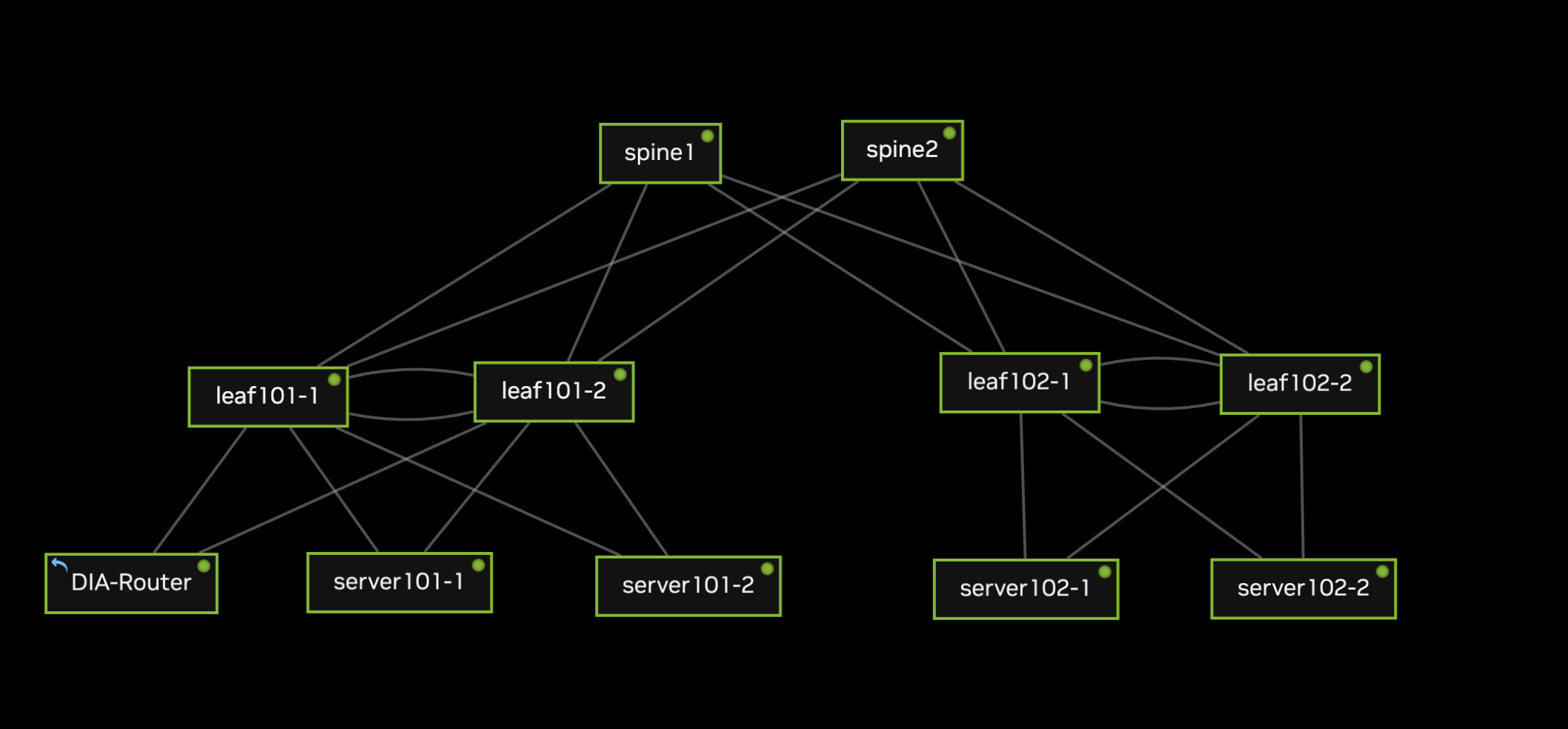
This is a straightforward spine-leaf topology consisting of two spines, two leaf pairs, four servers, and a dedicated switch which is configured to allow our virtual lab to reach the internet (“DIA-Router”). Here are some useful facts to review about our network before we start:
Each leaf pair utilizes MLAG to provide multi-chassis redundancy for the servers as well as DIA-Router.
The spines are configured as the EVPN route servers.
Each leaf has two loopbacks - one functions as the RID and is used for EVPN, and the other is used as the shared MLAG IP address.
We include two VLANs in our VXLAN fabric: VLAN 10 (192.168.10.0/24) and VLAN 20 (192.168.20.0/24)
DIA-Router is placed in a special edge subnet, VLAN 99 (192.168.99.0/29). This is not included in VXLAN, but it is advertised by BGP.
The interfaces in our lab are connected as follows. Be sure to do all of this before you start your lab! You can’t edit connections or add devices after you’ve started for the first time:
spine1 swp1 <-> leaf101-1 swp1
spine1 swp2 <-> leaf101-2 swp1
spine1 swp3 <-> leaf102-1 swp1
spine1 swp4 <-> leaf102-2 swp1

spine2 swp1 <-> leaf101-1 swp2
spine2 swp2 <-> leaf101-2 swp2
spine2 swp3 <-> leaf102-1 swp2
spine2 swp4 <-> leaf102-2 swp2

leaf101-1 swp28 <-> server101-2 eth0
leaf101-1 swp29 <-> server101-1 eth0
leaf101-1 swp30 <-> DIA-Router swp1
leaf101-1 swp31 <-> leaf101-2 swp31
leaf101-1 swp32 <-> leaf101-2 swp32

leaf101-2 swp28 <-> server101-2 eth1
leaf101-2 swp29 <-> server101-1 eth1
leaf101-2 swp30 <-> DIA-Router swp2
leaf101-2 swp31 <-> leaf101-2 swp31
leaf101-2 swp32 <-> leaf101-2 swp32

leaf102-1 swp29 <-> server102-2 eth0
leaf102-1 swp30 <-> server102-1 eth0
leaf102-1 swp31 <-> leaf102-2 swp31
leaf102-1 swp32 <-> leaf102-2 swp32

leaf102-2 swp29 <-> server102-2 eth1
leaf102-2 swp30 <-> server102-1 eth1
leaf102-2 swp31 <-> leaf102-2 swp31
leaf102-2 swp32 <-> leaf102-2 swp32

DIA-Router swp32 --> Outbound Port (Internet)
switches:
  spine1:
    loopback_primary:   10.255.0.1/32
    asn: 65501
  spine2:
    loopback_primary:   10.255.0.2/32
    asn: 65502
  leaf101-1:
    loopback_primary:   10.255.0.3/32
    loopback_secondary: 10.254.0.1/32
    asn: 65101
  leaf101-2:
    loopback_primary:   10.255.0.4/32
    loopback_secondary: 10.254.0.1/32
    asn: 65101
  leaf102-1:
    loopback_primary:   10.255.0.5/32
    loopback_secondary: 10.254.0.2/32
    asn: 65102
  leaf102-2:
    loopback_primary:   10.255.0.6/32
    loopback_secondary: 10.254.0.2/32
    asn: 65102
  DIA-Router:
    loopback_primary: 10.255.0.99/32
Configuration
Nvidia Cumulus ships with the Nvidia User Experience (NVUE) package, which mimics the functionality of a network operating system like Cisco IOS or Arista EOS. It is possible to configure Cumulus using normal Linux conventions (e.g. FRR, configuration files) or NVUE, but not both. This is because NVUE overwrites the network configs in Cumulus when a configuration is applied to the switch. We will use NVUE almost exclusively for configuration in this lab, with the exception of NAT configurations on the DIA-Router which are not supported in Nvidia Air’s version of NVUE.
Basic System Configurations
The first order of business is to log into the switches and change the default credentials, which are cumulus/cumulus. The OS will prompt you for a new password for the cumulus user. Optionally you can also disable the ZTP daemon as instructed in the help output:
Debian GNU/Linux 10 cumulus ttyS0

cumulus login: cumulus
Password:
You are required to change your password immediately (administrator enforced)
Changing password for cumulus.
Current password:
New password:
Retype new password:
Last login: Tue Sep  5 06:59:59 UTC 2023 from 10.0.2.2 on pts/0
Linux cumulus 5.10.0-cl-1-amd64 #1 SMP Debian 5.10.179-1+cl5.6.0u25 (2023-08-04) x86_64

Welcome to NVIDIA Cumulus VX (TM)

NVIDIA Cumulus VX (TM) is a community supported virtual appliance designed
for experiencing, testing and prototyping NVIDIA Cumulus' latest technology.
For any questions or technical support, visit our community site at:
https://www.nvidia.com/en-us/support

The registered trademark Linux (R) is used pursuant to a sublicense from LMI,
the exclusive licensee of Linus Torvalds, owner of the mark on a world-wide
basis.

ZTP in progress. To disable, do 'ztp -d'

cumulus@cumulus:mgmt:~$ sudo ztp -d
[sudo] password for cumulus:
Removed /etc/systemd/system/multi-user.target.wants/ztp.service.
Using the default cumulus user for a lab is fine, but if you’d like to log in with your own user account instead, you can configure that like you would on any other Debian-based OS:
cumulus@cumulus:mgmt:~$ sudo useradd -d /home/jelliott -G sudo -m jelliott
cumulus@cumulus:mgmt:~$ sudo passwd jelliott
New password:
Retype new password:
passwd: password updated successfully
cumulus@cumulus:mgmt:~$ exit
logout

Debian GNU/Linux 10 cumulus ttyS0

cumulus login: jelliott
Password:
Linux cumulus 5.10.0-cl-1-amd64 #1 SMP Debian 5.10.179-1+cl5.6.0u25 (2023-08-04) x86_64

Welcome to NVIDIA Cumulus VX (TM)
$
Now we can set basic system configurations like hostname, DNS servers, and NTP. Except for the hostname, this config will be the same for every switch, so we’ll just use leaf101-1 as an example:
$ sudo su
[sudo] password for jelliott:
root@cumulus:mgmt:~# nv set system hostname leaf101-1
root@cumulus:mgmt:~# nv set system timezone US/Central
root@cumulus:mgmt:~# nv config apply
Warning: The following files have been changed since the last save, and they WILL be overwritten.
        - /etc/synced/synced.conf
        - /etc/cumulus/switchd.conf
        - /etc/cumulus/switchd.d/ptp.conf
        - /etc/cumulus/datapath/qos/qos_features.conf
        - /etc/mlx/datapath/qos/qos_infra.conf
        - /etc/cumulus/switchd.d/qos.conf
        - /etc/cumulus/ports.conf
        - /etc/cumulus/ports_width.conf
        - /etc/ntp.conf
        - /etc/default/lldpd
        - /etc/ptp4l.conf
        - /etc/network/interfaces
        - /etc/frr/frr.conf
        - /etc/frr/daemons
        - /etc/hosts
        - /etc/dhcp/dhclient-exit-hooks.d/dhcp-sethostname
        - /etc/hostname
        - /etc/ssh/sshd_config
        - /etc/resolv.conf
        - /etc/cumulus/control-plane/policers.conf
Warning: The frr service will need to be restarted because the list of router services has changed.  This will disrupt traffic for any existing routing protocols.
Warning: current hostname `cumulus` will be replaced with `leaf101-1`

Are you sure? [y/N] y
applied [rev_id: 1]
root@cumulus:mgmt:~# nv config save
saved [rev_id: applied]
Changes in NVUE are staged before they are applied to the running configuration. When we use nv config apply, this applies the staged commands to the running configuration of the device, but this alone does not save the configuration persistently across reboots. To make sure our startup configuration file matches our current running configuration, we need to use nv config save.
If you would like NVUE to copy your updates to the switch’s startup configuration automatically, you can set NVUE to autosave upon a successful nv config apply like we did below. Note that the completion message now reads applied_and_saved instead of just applied:
root@cumulus:mgmt:~# nv set system config auto-save enable
root@cumulus:mgmt:~# nv config apply
applied_and_saved [rev_id: 2]
Point-to-Point Links
After each switch has some basic configs, the next order of business is to configure the uplinks. Our lab uses the 10.0.0.0/24 space for uplinks, which is broken down into /31 subnets. If you’re unfamiliar with /31 subnets, check out the relevant section in our subnetting guide for more information.
In NVUE, the set and unset commands are used to enable or disable an interface. Therefore we first use nv set interface {interface} to enable the interface, then we set the IP address for each interface:
root@spine1:mgmt:~# nv set interface swp1
root@spine1:mgmt:~# nv set interface swp2
root@spine1:mgmt:~# nv set interface swp3
root@spine1:mgmt:~# nv set interface swp4
root@spine1:mgmt:~# nv set interface swp1 ip address 10.0.0.0/31
root@spine1:mgmt:~# nv set interface swp2 ip address 10.0.0.4/31
root@spine1:mgmt:~# nv set interface swp3 ip address 10.0.0.8/31
root@spine1:mgmt:~# nv set interface swp4 ip address 10.0.0.12/31
root@spine1:mgmt:~# nv config apply
applied_and_saved [rev_id: 3]

root@spine2:mgmt:~# nv set interface swp1
root@spine2:mgmt:~# nv set interface swp2
root@spine2:mgmt:~# nv set interface swp3
root@spine2:mgmt:~# nv set interface swp4
root@spine2:mgmt:~# nv set interface swp1 ip address 10.0.0.2/31
root@spine2:mgmt:~# nv set interface swp2 ip address 10.0.0.6/31
root@spine2:mgmt:~# nv set interface swp3 ip address 10.0.0.10/31
root@spine2:mgmt:~# nv set interface swp4 ip address 10.0.0.14/31
root@spine2:mgmt:~# nv config apply
applied_and_saved [rev_id: 3]

root@leaf101-1:mgmt:~# nv set interface swp1
root@leaf101-1:mgmt:~# nv set interface swp2
root@leaf101-1:mgmt:~# nv set interface swp1 ip address 10.0.0.1/31
root@leaf101-1:mgmt:~# nv set interface swp2 ip address 10.0.0.3/31
root@leaf101-1:mgmt:~# nv config apply
applied_and_saved [rev_id: 3]

root@leaf101-2:mgmt:~# nv set interface swp1
root@leaf101-2:mgmt:~# nv set interface swp2
root@leaf101-2:mgmt:~# nv set interface swp1 ip address 10.0.0.5/31
root@leaf101-2:mgmt:~# nv set interface swp2 ip address 10.0.0.7/31
root@leaf101-2:mgmt:~# nv config apply
applied_and_saved [rev_id: 2]

root@leaf102-1:mgmt:~# nv set interface swp1
root@leaf102-1:mgmt:~# nv set interface swp2
root@leaf102-1:mgmt:~# nv set interface swp1 ip address 10.0.0.9/31
root@leaf102-1:mgmt:~# nv set interface swp2 ip address 10.0.0.11/31
root@leaf102-1:mgmt:~# nv config apply
applied_and_saved [rev_id: 2]

root@leaf102-2:mgmt:~# nv set interface swp1
root@leaf102-2:mgmt:~# nv set interface swp2
root@leaf102-2:mgmt:~# nv set interface swp1 ip address 10.0.0.13/31
root@leaf102-2:mgmt:~# nv set interface swp2 ip address 10.0.0.15/31
root@leaf102-2:mgmt:~# nv config apply
applied_and_saved [rev_id: 2]
There’s a variety of methods to verify IP address configurations on Cumulus. You can use NVUE, FRR, Linux commands, or network configuration files. Here are a few ways to do it, using leaf101-1 as an example:
# Using iproute2
root@leaf101-1:mgmt:~# ip addr show swp1 | grep inet
    inet 10.0.0.1/31 scope global swp1
    inet6 fe80::4ab0:2dff:fe4c:5b6b/64 scope link
root@leaf101-1:mgmt:~# ip addr show swp2 | grep inet
    inet 10.0.0.3/31 scope global swp2
    inet6 fe80::4ab0:2dff:fec5:45ce/64 scope link

# Using FRR
root@leaf101-1:mgmt:~# vtysh

Hello, this is FRRouting (version 8.4.3).
Copyright 1996-2005 Kunihiro Ishiguro, et al.

leaf101-1# show interface brief
Interface       Status  VRF             Addresses
---------       ------  ---             ---------
lo              up      default
swp1            up      default         10.0.0.1/31
swp2            up      default         10.0.0.3/31
...

# Using 'nv config find'

root@leaf101-1:mgmt:~# nv config find ip
- set:
    interface:
      swp1:
        ip:
          address:
            10.0.0.1/31: {}
      swp2:
        ip:
          address:
            10.0.0.3/31: {}
Loopback Interfaces
Configuring IP addresses for the loopback interface is similar to what we did for the physical interfaces, except for each leaf we need to configure two IPs on the same interface. The first loopback (10.255.0.X) will be used as the Router ID, and the second loopback (10.254.0.X) will be the shared VXLAN source address between two leaf switches in a pair.
# Spines only need the primary loopback

root@spine1:mgmt:~# nv set interface lo ip address 10.255.0.1/32
root@spine1:mgmt:~# nv config apply
applied_and_saved [rev_id: 4]

root@spine2:mgmt:~# nv set interface lo ip address 10.255.0.2/32
root@spine2:mgmt:~# nv config apply
applied_and_saved [rev_id: 5]

# Leaves need a unique RID and a shared VTEP address.
# The VTEP address will be shared between MLAG peers.

root@leaf101-1:mgmt:~# nv set interface lo ip address 10.255.0.3/32
root@leaf101-1:mgmt:~# nv set interface lo ip address 10.254.0.1/32
root@leaf101-1:mgmt:~# nv config apply
applied_and_saved [rev_id: 4]
root@leaf101-1:mgmt:~# nv config find lo
- set:
    interface:
      lo:
        ip:
          address:
            10.254.0.1/32: {}
            10.255.0.3/32: {}
        type: loopback

root@leaf101-2:mgmt:~# nv set interface lo ip address 10.255.0.4/32
root@leaf101-2:mgmt:~# nv set interface lo ip address 10.254.0.1/32
root@leaf101-2:mgmt:~# nv config apply
applied_and_saved [rev_id: 3]
root@leaf101-2:mgmt:~# nv config find lo
- set:
    interface:
      lo:
        ip:
          address:
            10.254.0.1/32: {}
            10.255.0.4/32: {}
        type: loopback

root@leaf102-1:mgmt:~# nv set interface lo ip address 10.255.0.5/32
root@leaf102-1:mgmt:~# nv set interface lo ip address 10.254.0.2/32
root@leaf102-1:mgmt:~# nv config apply
applied_and_saved [rev_id: 2]
root@leaf102-1:mgmt:~# nv config find lo
- set:
    interface:
      lo:
        ip:
          address:
            10.254.0.2/32: {}
            10.255.0.5/32: {}
        type: loopback

root@leaf102-2:mgmt:~# nv set interface lo ip address 10.255.0.6/32
root@leaf102-2:mgmt:~# nv set interface lo ip address 10.254.0.2/32
root@leaf102-2:mgmt:~# nv config apply
applied_and_saved [rev_id: 2]
root@leaf102-2:mgmt:~# nv config find lo
- set:
    interface:
      lo:
        ip:
          address:
            10.254.0.2/32: {}
            10.255.0.6/32: {}
        type: loopback
BGP Routing (Underlay)
Now that we have some IP addresses to work with, let’s spin up BGP to serve as the underlay network for our VXLAN/EVPN fabric. For each switch, we’ll need to define the Router ID, ASN, and peers at minimum to achieve basic routing. Additionally, we’ll configure some optional features to match a typical data center BGP design, such as BFD, ECMP, communities, route maps, and soft reconfiguration.
We’ll start with the spine configurations and move onto the leaves afterwards:
# Mandatory BGP Configs
root@spine1:mgmt:~# nv set router bgp enable
root@spine1:mgmt:~# nv set router bgp autonomous-system 65501
root@spine1:mgmt:~# nv set router bgp router-id 10.255.0.1

# Define a peer group to reduce redundant per-peer configs
root@spine1:mgmt:~# nv set vrf default router bgp peer-group leaf-switches

# Enable BFD
root@spine1:mgmt:~# nv set vrf default router bgp peer-group leaf-switches bfd enable

# Adjust timers
root@spine1:mgmt:~# nv set vrf default router bgp peer-group leaf-switches timers keepalive 3
root@spine1:mgmt:~# nv set vrf default router bgp peer-group leaf-switches timers hold 9

# Enable soft inbound reconfiguration
root@spine1:mgmt:~# nv set vrf default router bgp peer-group leaf-switches address-family ipv4-unicast soft-reconfiguration on

# Enable extended communities
root@spine1:mgmt:~# nv set vrf default router bgp peer-group leaf-switches address-family ipv4-unicast community-advertise extended on

# Include your peers in the peer group
root@spine1:mgmt:~# nv set vrf default router bgp neighbor 10.0.0.1 peer-group leaf-switches
root@spine1:mgmt:~# nv set vrf default router bgp neighbor 10.0.0.5 peer-group leaf-switches
root@spine1:mgmt:~# nv set vrf default router bgp neighbor 10.0.0.9 peer-group leaf-switches
root@spine1:mgmt:~# nv set vrf default router bgp neighbor 10.0.0.13 peer-group leaf-switches

# Define the remote-as for each peer
root@spine1:mgmt:~# nv set vrf default router bgp neighbor 10.0.0.1 remote-as 65101
root@spine1:mgmt:~# nv set vrf default router bgp neighbor 10.0.0.5 remote-as 65101
root@spine1:mgmt:~# nv set vrf default router bgp neighbor 10.0.0.9 remote-as 65102
root@spine1:mgmt:~# nv set vrf default router bgp neighbor 10.0.0.13 remote-as 65102

# Create a route map
root@spine1:mgmt:~# nv set router policy route-map redistribute-to-bgp rule 1 match interface lo
root@spine1:mgmt:~# nv set router policy route-map redistribute-to-bgp rule 1 action permit

# Redistribute connected routes and filter them with our route map
root@spine1:mgmt:~# nv set vrf default router bgp address-family ipv4-unicast redistribute connected route-map redistribute-to-bgp
We’ll configure spine2 in the same way, with the appropriate variables:
root@spine2:mgmt:~# nv set router bgp enable
root@spine2:mgmt:~# nv set router bgp autonomous-system 65502
root@spine2:mgmt:~# nv set router bgp router-id 10.255.0.2
root@spine2:mgmt:~# nv set vrf default router bgp peer-group leaf-switches
root@spine2:mgmt:~# nv set vrf default router bgp peer-group leaf-switches bfd enable
root@spine2:mgmt:~# nv set vrf default router bgp peer-group leaf-switches timers keepalive 3
root@spine2:mgmt:~# nv set vrf default router bgp peer-group leaf-switches timers hold 9
root@spine2:mgmt:~# nv set vrf default router bgp peer-group leaf-switches address-family ipv4-unicast soft-reconfiguration on
root@spine2:mgmt:~# nv set vrf default router bgp peer-group leaf-switches address-family ipv4-unicast community-advertise extended on
root@spine2:mgmt:~# nv set vrf default router bgp neighbor 10.0.0.3 remote-as 65101
root@spine2:mgmt:~# nv set vrf default router bgp neighbor 10.0.0.7 remote-as 65101
root@spine2:mgmt:~# nv set vrf default router bgp neighbor 10.0.0.11 remote-as 65102
root@spine2:mgmt:~# nv set vrf default router bgp neighbor 10.0.0.15 remote-as 65102
root@spine2:mgmt:~# nv set vrf default router bgp neighbor 10.0.0.3 peer-group leaf-switches
root@spine2:mgmt:~# nv set vrf default router bgp neighbor 10.0.0.7 peer-group leaf-switches
root@spine2:mgmt:~# nv set vrf default router bgp neighbor 10.0.0.11 peer-group leaf-switches
root@spine2:mgmt:~# nv set vrf default router bgp neighbor 10.0.0.15 peer-group leaf-switches
root@spine2:mgmt:~# nv set router policy route-map redistribute-to-bgp rule 1 match interface lo
root@spine2:mgmt:~# nv set router policy route-map redistribute-to-bgp rule 1 action permit
root@spine2:mgmt:~# nv set vrf default router bgp address-family ipv4-unicast redistribute connected route-map redistribute-to-bgp
The leaves are configured in a similar manner, with some important differences. Leaves will use eBGP to peer with the spines, but they will also use iBGP to peer with their respective MLAG peers. In other words, leaf101-1 and leaf101-2 will peer with each other using iBGP over their MLAG peer link, and they will also peer with the spines using eBGP. Furthermore, each leaf will have two equal cost paths to remote networks via the spines, so we will need to ensure that ECMP is enabled to make use of the equal cost paths available to each leaf.
# Mandatory BGP configs
root@leaf101-1:mgmt:~# nv set router bgp enable
root@leaf101-1:mgmt:~# nv set router bgp autonomous-system 65101
root@leaf101-1:mgmt:~# nv set router bgp router-id 10.255.0.3

# Configure ECMP. We have two spines, so we have two equal cost paths
# to remote networks that we learn via BGP.
root@leaf101-1:mgmt:~# nv set vrf default router bgp address-family ipv4-unicast multipaths ebgp 2

# Create a peer group to minimize redundant configs
root@leaf101-1:mgmt:~# nv set vrf default router bgp peer-group spines

# Match optional settings with the spines
root@leaf101-1:mgmt:~# nv set vrf default router bgp peer-group spines bfd enable
root@leaf101-1:mgmt:~# nv set vrf default router bgp peer-group spines timers keepalive 3
root@leaf101-1:mgmt:~# nv set vrf default router bgp peer-group spines timers hold 9
root@leaf101-1:mgmt:~# nv set vrf default router bgp peer-group spines address-family ipv4-unicast soft-reconfiguration on
root@leaf101-1:mgmt:~# nv set vrf default router bgp peer-group spines address-family ipv4-unicast community-advertise extended on

# Define the remote ASNs of the spines
root@leaf101-1:mgmt:~# nv set vrf default router bgp neighbor 10.0.0.0 remote-as 65501
root@leaf101-1:mgmt:~# nv set vrf default router bgp neighbor 10.0.0.2 remote-as 65502

# Attach the spines to the peer group
root@leaf101-1:mgmt:~# nv set vrf default router bgp neighbor 10.0.0.0 peer-group spines
root@leaf101-1:mgmt:~# nv set vrf default router bgp neighbor 10.0.0.2 peer-group spines

# Configure a route map to filter redistributed routes
root@leaf101-1:mgmt:~# nv set router policy route-map redistribute-to-bgp rule 1 match interface lo
root@leaf101-1:mgmt:~# nv set router policy route-map redistribute-to-bgp rule 1 action permit

# Redistribute loopback prefixes into BGP
root@leaf101-1:mgmt:~# nv set vrf default router bgp address-family ipv4-unicast redistribute connected route-map redistribute-to-bgp

# Apply the config
root@leaf101-1:mgmt:~# nv config apply
Warning: The following files have been changed since the last save, and they WILL be overwritten.
        - /etc/cumulus/switchd.d/kernel_route_offload_flags.conf
Warning: Switchd need to restart on this config change
Warning: The frr service will need to be restarted because the list of router services has changed.  This will disrupt traffic for any existing routing protocols.

Are you sure? [y/N] y
applied_and_saved [rev_id: 5]
You might have noticed that we didn’t include the iBGP connection in leaf101-1’s configuration. That was intentional. We will configure the iBGP peering relationships when we set up our VLANs, SVIs, and MLAG in the following sections. For now, let’s finish up the eBGP configurations for each leaf and then validate that our peers are established:
# leaf101-2
root@leaf101-2:mgmt:~# nv set router bgp enable
root@leaf101-2:mgmt:~# nv set router bgp autonomous-system 65101
root@leaf101-2:mgmt:~# nv set router bgp router-id 10.255.0.4
root@leaf101-2:mgmt:~# nv set vrf default router bgp address-family ipv4-unicast multipaths ebgp 2
root@leaf101-2:mgmt:~# nv set vrf default router bgp peer-group spines
root@leaf101-2:mgmt:~# nv set vrf default router bgp peer-group spines bfd enable
root@leaf101-2:mgmt:~# nv set vrf default router bgp peer-group spines timers keepalive 3
root@leaf101-2:mgmt:~# nv set vrf default router bgp peer-group spines timers hold 9
root@leaf101-2:mgmt:~# nv set vrf default router bgp peer-group spines address-family ipv4-unicast soft-reconfiguration on
root@leaf101-2:mgmt:~# nv set vrf default router bgp peer-group spines address-family ipv4-unicast community-advertise extended on
root@leaf101-2:mgmt:~# nv set vrf default router bgp neighbor 10.0.0.4 remote-as 65501
root@leaf101-2:mgmt:~# nv set vrf default router bgp neighbor 10.0.0.6 remote-as 65502
root@leaf101-2:mgmt:~# nv set vrf default router bgp neighbor 10.0.0.4 peer-group spines
root@leaf101-2:mgmt:~# nv set vrf default router bgp neighbor 10.0.0.6 peer-group spines
root@leaf101-2:mgmt:~# nv set router policy route-map redistribute-to-bgp rule 1 match interface lo
root@leaf101-2:mgmt:~# nv set router policy route-map redistribute-to-bgp rule 1 action permit
root@leaf101-2:mgmt:~# nv set vrf default router bgp address-family ipv4-unicast redistribute connected route-map redistribute-to-bgp

# leaf102-1
root@leaf102-1:mgmt:~# nv set router bgp enable
root@leaf102-1:mgmt:~# nv set router bgp autonomous-system 65102
root@leaf102-1:mgmt:~# nv set router bgp router-id 10.255.0.5
root@leaf102-1:mgmt:~# nv set vrf default router bgp address-family ipv4-unicast multipaths ebgp 2
root@leaf102-1:mgmt:~# nv set vrf default router bgp peer-group spines
root@leaf102-1:mgmt:~# nv set vrf default router bgp peer-group spines bfd enable
root@leaf102-1:mgmt:~# nv set vrf default router bgp peer-group spines timers keepalive 3
root@leaf102-1:mgmt:~# nv set vrf default router bgp peer-group spines timers hold 9
root@leaf102-1:mgmt:~# nv set vrf default router bgp peer-group spines address-family ipv4-unicast soft-reconfiguration on
root@leaf102-1:mgmt:~# nv set vrf default router bgp peer-group spines address-family ipv4-unicast community-advertise extended on
root@leaf102-1:mgmt:~# nv set vrf default router bgp neighbor 10.0.0.8 remote-as 65501
root@leaf102-1:mgmt:~# nv set vrf default router bgp neighbor 10.0.0.10 remote-as 65502
root@leaf102-1:mgmt:~# nv set vrf default router bgp neighbor 10.0.0.8 peer-group spines
root@leaf102-1:mgmt:~# nv set vrf default router bgp neighbor 10.0.0.10 peer-group spines
root@leaf102-1:mgmt:~# nv set router policy route-map redistribute-to-bgp rule 1 match interface lo
root@leaf102-1:mgmt:~# nv set router policy route-map redistribute-to-bgp rule 1 action permit
root@leaf102-1:mgmt:~# nv set vrf default router bgp address-family ipv4-unicast redistribute connected route-map redistribute-to-bgp

#leaf102-2
root@leaf102-2:mgmt:~# nv set router bgp enable
root@leaf102-2:mgmt:~# nv set router bgp autonomous-system 65102
root@leaf102-2:mgmt:~# nv set router bgp router-id 10.255.0.6
root@leaf102-2:mgmt:~# nv set vrf default router bgp address-family ipv4-unicast multipaths ebgp 2
root@leaf102-2:mgmt:~# nv set vrf default router bgp peer-group spines
root@leaf102-2:mgmt:~# nv set vrf default router bgp peer-group spines bfd enable
root@leaf102-2:mgmt:~# nv set vrf default router bgp peer-group spines timers keepalive 3
root@leaf102-2:mgmt:~# nv set vrf default router bgp peer-group spines timers hold 9
root@leaf102-2:mgmt:~# nv set vrf default router bgp peer-group spines address-family ipv4-unicast soft-reconfiguration on
root@leaf102-2:mgmt:~# nv set vrf default router bgp peer-group spines address-family ipv4-unicast community-advertise extended on
root@leaf102-2:mgmt:~# nv set vrf default router bgp neighbor 10.0.0.12 remote-as 65501
root@leaf102-2:mgmt:~# nv set vrf default router bgp neighbor 10.0.0.14 remote-as 65502
root@leaf102-2:mgmt:~# nv set vrf default router bgp neighbor 10.0.0.12 peer-group spines
root@leaf102-2:mgmt:~# nv set vrf default router bgp neighbor 10.0.0.14 peer-group spines
root@leaf102-2:mgmt:~# nv set router policy route-map redistribute-to-bgp rule 1 match interface lo
root@leaf102-2:mgmt:~# nv set router policy route-map redistribute-to-bgp rule 1 action permit
root@leaf102-2:mgmt:~# nv set vrf default router bgp address-family ipv4-unicast redistribute connected route-map redistribute-to-bgp
Let’s verify that our peering relationships are established and that we’re learning routes via BGP. We can test this out from one of the spines:
root@spine1:mgmt:~# nv show vrf default router bgp neighbor

AS - Remote Autonomous System, Afi-Safi - Address family, PfxSent - Transmitted
prefix counter, PfxRcvd - Recieved prefix counter

Neighbor   AS     State        Uptime    ResetTime  MsgRcvd  MsgSent  Afi-Safi      PfxSent  PfxRcvd
---------  -----  -----------  --------  ---------  -------  -------  ------------  -------  -------
10.0.0.1   65101  established  00:37:34  5373000    759      761      ipv4-unicast  8        3
10.0.0.5   65101  established  00:17:17  5373000    353      355      ipv4-unicast  8        3
10.0.0.9   65102  established  00:15:25  5373000    316      317      ipv4-unicast  8        3
10.0.0.13  65102  established  00:13:08  5373000    270      271      ipv4-unicast  8        3
root@spine1:mgmt:~#
root@spine1:mgmt:~# vtysh

Hello, this is FRRouting (version 8.4.3).
Copyright 1996-2005 Kunihiro Ishiguro, et al.

spine1# show ip route
Codes: K - kernel route, C - connected, S - static, R - RIP,
       O - OSPF, I - IS-IS, B - BGP, E - EIGRP, N - NHRP,
       T - Table, A - Babel, D - SHARP, F - PBR, f - OpenFabric,
       Z - FRR,
       > - selected route, * - FIB route, q - queued, r - rejected, b - backup
       t - trapped, o - offload failure

C>* 10.0.0.0/31 is directly connected, swp1, 02:46:17
C>* 10.0.0.4/31 is directly connected, swp2, 02:46:17
C>* 10.0.0.8/31 is directly connected, swp3, 02:46:17
C>* 10.0.0.12/31 is directly connected, swp4, 02:46:17
B>* 10.254.0.1/32 [20/0] via 10.0.0.1, swp1, weight 1, 00:08:37
  *                      via 10.0.0.5, swp2, weight 1, 00:08:37
B>* 10.254.0.2/32 [20/0] via 10.0.0.9, swp3, weight 1, 00:13:15
  *                      via 10.0.0.13, swp4, weight 1, 00:13:15
C>* 10.255.0.1/32 is directly connected, lo, 02:46:17
B>* 10.255.0.2/32 [20/0] via 10.0.0.1, swp1, weight 1, 00:17:23
  *                      via 10.0.0.5, swp2, weight 1, 00:17:23
B>* 10.255.0.3/32 [20/0] via 10.0.0.1, swp1, weight 1, 00:08:37
B>* 10.255.0.4/32 [20/0] via 10.0.0.5, swp2, weight 1, 00:17:24
B>* 10.255.0.5/32 [20/0] via 10.0.0.9, swp3, weight 1, 00:15:32
B>* 10.255.0.6/32 [20/0] via 10.0.0.13, swp4, weight 1, 00:13:15
As you can see, the spines are learning both loopback addresses from each of the leaves. As expected, the shared VXLAN loopback addresses are being learned from both members of each MLAG pair. For good measure, let’s check reachability to the primary loopback IPs on each leaf:
spine1# ping 10.255.0.3
vrf-wrapper.sh: switching to vrf "default"; use '--no-vrf-switch' to disable
PING 10.255.0.3 (10.255.0.3) 56(84) bytes of data.
64 bytes from 10.255.0.3: icmp_seq=1 ttl=64 time=0.583 ms
64 bytes from 10.255.0.3: icmp_seq=2 ttl=64 time=0.642 ms
...

spine1# ping 10.255.0.4
vrf-wrapper.sh: switching to vrf "default"; use '--no-vrf-switch' to disable
PING 10.255.0.4 (10.255.0.4) 56(84) bytes of data.
64 bytes from 10.255.0.4: icmp_seq=1 ttl=64 time=0.627 ms
64 bytes from 10.255.0.4: icmp_seq=2 ttl=64 time=0.672 ms
...

spine1# ping 10.255.0.5
vrf-wrapper.sh: switching to vrf "default"; use '--no-vrf-switch' to disable
PING 10.255.0.5 (10.255.0.5) 56(84) bytes of data.
64 bytes from 10.255.0.5: icmp_seq=1 ttl=64 time=0.668 ms
64 bytes from 10.255.0.5: icmp_seq=2 ttl=64 time=0.699 ms
...

spine1# ping 10.255.0.6
vrf-wrapper.sh: switching to vrf "default"; use '--no-vrf-switch' to disable
PING 10.255.0.6 (10.255.0.6) 56(84) bytes of data.
64 bytes from 10.255.0.6: icmp_seq=1 ttl=64 time=0.853 ms
64 bytes from 10.255.0.6: icmp_seq=2 ttl=64 time=0.589 ms
MLAG
Now that our eBGP underlay is established, we need to establish iBGP relationships between leaf pairs. This step was intentionally absent from the previous section, because it is closely tied to MLAG configuration for reasons which will become apparent soon. Let’s begin by configuring MLAG and iBGP between leaf101-1 and leaf101-2:
# Configure an LACP bond to function as the MLAG peer link
root@leaf101-1:mgmt:~# nv set interface peerlink type bond
root@leaf101-1:mgmt:~# nv set interface peerlink bond mode lacp
root@leaf101-1:mgmt:~# nv set interface peerlink bond lacp-rate fast
root@leaf101-1:mgmt:~# nv set interface peerlink bond member swp31-32

# Add the peer link to the default bridge domain
root@leaf101-1:mgmt:~# nv set interface peerlink bridge domain br_default

# When a bond called "peerlink" is configured, a new interface
# called "peerlink.4094" is created automatically. Let's give it
# an IP address to use for MLAG and BGP.

root@leaf101-1:mgmt:~# nv set interface peerlink.4094 ip address 169.254.254.0/31

# Enable MLAG
root@leaf101-1:mgmt:~# nv set mlag enable on

# Define the MLAG peer IP address
root@leaf101-1:mgmt:~# nv set mlag peer-ip 169.254.254.1

# Define the backup peer IP address
root@leaf101-1:mgmt:~# nv set mlag backup 10.255.0.4

# Set the MLAG MAC address. This must match on both MLAG peers.
root@leaf101-1:mgmt:~# nv set mlag mac-address 44:38:39:BE:EF:AA

# Configure the iBGP relationship
root@leaf101-1:mgmt:~# nv set vrf default router bgp neighbor 169.254.254.1 remote-as 65101
root@leaf101-1:mgmt:~# nv set vrf default router bgp neighbor 169.254.254.1 timer keepalive 3
root@leaf101-1:mgmt:~# nv set vrf default router bgp neighbor 169.254.254.1 timer hold 9
root@leaf101-1:mgmt:~# nv set vrf default router bgp neighbor 169.254.254.1 bfd enable
root@leaf101-1:mgmt:~# nv set vrf default router bgp neighbor 169.254.254.1 address-family ipv4-unicast nexthop-setting self
root@leaf101-1:mgmt:~# nv set vrf default router bgp neighbor 169.254.254.1 address-family ipv4-unicast community-advertise extended on

# Apply and save the config
root@leaf101-1:mgmt:~# nv config apply
applied_and_saved [rev_id: 9]

# On leaf101-2
root@leaf101-2:mgmt:~# nv set interface peerlink type bond
root@leaf101-2:mgmt:~# nv set interface peerlink bond mode lacp
root@leaf101-2:mgmt:~# nv set interface peerlink bond lacp-rate fast
root@leaf101-2:mgmt:~# nv set interface peerlink bond member swp31-32
root@leaf101-2:mgmt:~# nv set interface peerlink bridge domain br_default
root@leaf101-2:mgmt:~# nv set mlag enable on
root@leaf101-2:mgmt:~# nv set mlag peer-ip 169.254.254.0
root@leaf101-2:mgmt:~# nv set mlag backup 10.255.0.3
root@leaf101-2:mgmt:~# nv set mlag mac-address 44:38:39:BE:EF:AA
root@leaf101-2:mgmt:~# nv set interface peerlink.4094 ip address 169.254.254.1/31
root@leaf101-2:mgmt:~# nv set vrf default router bgp neighbor 169.254.254.0 remote-as 65101
root@leaf101-2:mgmt:~# nv set vrf default router bgp neighbor 169.254.254.0 timer keepalive 3
root@leaf101-2:mgmt:~# nv set vrf default router bgp neighbor 169.254.254.0 timer hold 9
root@leaf101-2:mgmt:~# nv set vrf default router bgp neighbor 169.254.254.0 bfd enable
root@leaf101-2:mgmt:~# nv set vrf default router bgp neighbor 169.254.254.0 address-family ipv4-unicast nexthop-setting self
root@leaf101-2:mgmt:~# nv set vrf default router bgp neighbor 169.254.254.0 address-family ipv4-unicast community-advertise extended on
root@leaf101-2:mgmt:~# nv config apply
applied_and_saved [rev_id: 9]
Let’s verify that MLAG and BGP are working between the two leaves now. We haven’t configured any VLANs or MLAG downlinks to test yet (we’ll do that in the next section), but we can still review the status and consistency of the MLAG relationship itself:
# Check our iBGP connection
root@leaf101-1:mgmt:~# nv show vrf default router bgp neighbor | grep 169
169.254.254.1  65101  established  00:12:52  2073000    265      267      ipv4-unicast

# Check MLAG status
root@leaf101-1:mgmt:~# nv show mlag
                operational        applied
--------------  -----------------  -----------------
enable          on                 on
debug           off                off
init-delay      180                180
mac-address     44:38:39:be:ef:aa  44:38:39:BE:EF:AA
peer-ip         169.254.254.1      169.254.254.1
priority        32768              32768
[backup]        10.255.0.4         10.255.0.4
backup-active   True
backup-reason
local-id        48:b0:2d:d1:45:fc
local-role      secondary
peer-alive      True
peer-id         48:b0:2d:75:3a:c2
peer-interface  peerlink.4094
peer-priority   32768
peer-role       primary

# Check MLAG config consistency. No conflicts = good!

root@leaf101-1:mgmt:~# nv show mlag consistency-checker
Global Consistency-checker
=============================
    Parameter               LocalValue         PeerValue          Conflict  Summary
    ----------------------  -----------------  -----------------  --------  -------
    anycast-ip              -                  -                  -
    bridge-priority         32768              32768              -
    bridge-stp              on                 on                 -
    bridge-type             vlan-aware         vlan-aware         -
    clag-pkg-version        1.6.0-cl5.6.0u15   1.6.0-cl5.6.0u15   -
    clag-protocol-version   1.6.1              1.6.1              -
    peer-ip                 169.254.254.1      169.254.254.1      -
    peerlink-bridge-member  Yes                Yes                -
    peerlink-mtu            9216               9216               -
    peerlink-native-vlan    1                  1                  -
    peerlink-vlans          1                  1                  -
    redirect2-enable        yes                yes                -
    system-mac              44:38:39:be:ef:aa  44:38:39:be:ef:aa  -
Let’s move onto the BGP and MLAG configs for leaf102-1 and leaf102-2:
# leaf102-1
root@leaf102-1:mgmt:~# nv set interface peerlink type bond
root@leaf102-1:mgmt:~# nv set interface peerlink bond mode lacp
root@leaf102-1:mgmt:~# nv set interface peerlink bond lacp-rate fast
root@leaf102-1:mgmt:~# nv set interface peerlink bond member swp31-32
root@leaf102-1:mgmt:~# nv set interface peerlink bridge domain br_default
root@leaf102-1:mgmt:~# nv set mlag enable on
root@leaf102-1:mgmt:~# nv set mlag peer-ip 169.254.254.1
root@leaf102-1:mgmt:~# nv set mlag backup 10.255.0.6
root@leaf102-1:mgmt:~# nv set mlag mac-address 44:38:39:BE:EF:AB
root@leaf102-1:mgmt:~# nv set interface peerlink.4094 ip address 169.254.254.0/31
root@leaf102-1:mgmt:~# nv set vrf default router bgp neighbor 169.254.254.1 remote-as 65102
root@leaf102-1:mgmt:~# nv set vrf default router bgp neighbor 169.254.254.1 timer keepalive 3
root@leaf102-1:mgmt:~# nv set vrf default router bgp neighbor 169.254.254.1 timer hold 9
root@leaf102-1:mgmt:~# nv set vrf default router bgp neighbor 169.254.254.1 bfd enable
root@leaf102-1:mgmt:~# nv set vrf default router bgp neighbor 169.254.254.1 address-family ipv4-unicast nexthop-setting self
root@leaf102-1:mgmt:~# nv set vrf default router bgp neighbor 169.254.254.1 address-family ipv4-unicast community-advertise extended on
root@leaf102-1:mgmt:~# nv config apply
applied_and_saved [rev_id: 4]

# leaf102-2
root@leaf102-2:mgmt:~# nv set interface peerlink type bond
root@leaf102-2:mgmt:~# nv set interface peerlink bond mode lacp
root@leaf102-2:mgmt:~# nv set interface peerlink bond lacp-rate fast
root@leaf102-2:mgmt:~# nv set interface peerlink bond member swp31-32
root@leaf102-2:mgmt:~# nv set interface peerlink bridge domain br_default
root@leaf102-2:mgmt:~# nv set mlag enable on
root@leaf102-2:mgmt:~# nv set mlag peer-ip 169.254.254.0
root@leaf102-2:mgmt:~# nv set mlag backup 10.255.0.5
root@leaf102-2:mgmt:~# nv set mlag mac-address 44:38:39:BE:EF:AB
root@leaf102-2:mgmt:~# nv set interface peerlink.4094 ip address 169.254.254.1/31
root@leaf102-2:mgmt:~# nv set vrf default router bgp neighbor 169.254.254.0 remote-as 65102
root@leaf102-2:mgmt:~# nv set vrf default router bgp neighbor 169.254.254.0 timer keepalive 3
root@leaf102-2:mgmt:~# nv set vrf default router bgp neighbor 169.254.254.0 timer hold 9
root@leaf102-2:mgmt:~# nv set vrf default router bgp neighbor 169.254.254.0 bfd enable
root@leaf102-2:mgmt:~# nv set vrf default router bgp neighbor 169.254.254.0 address-family ipv4-unicast nexthop-setting self
root@leaf102-2:mgmt:~# nv set vrf default router bgp neighbor 169.254.254.0 address-family ipv4-unicast community-advertise extended on
root@leaf102-2:mgmt:~# nv config apply
applied_and_saved [rev_id: 4]

# Let's validate from leaf102-2

root@leaf102-2:mgmt:~# nv show vrf default router bgp neighbor | grep 169
169.254.254.0  65102  established  00:00:20  24000      13       13       ipv4-unicast        7
root@leaf102-2:mgmt:~# nv show mlag
                operational        applied
--------------  -----------------  -----------------
enable          on                 on
debug           off                off
init-delay      180                180
mac-address     44:38:39:be:ef:ab  44:38:39:BE:EF:AB
peer-ip         169.254.254.0      169.254.254.0
priority        32768              32768
[backup]        10.255.0.5         10.255.0.5
backup-active   True
backup-reason
local-id        48:b0:2d:e1:4e:1f
local-role      secondary
peer-alive      True
peer-id         48:b0:2d:01:da:d0
peer-interface  peerlink.4094
peer-priority   32768
peer-role       primary
VLANs and Server Bonds
All of that work, and our servers still can’t talk to anything! Now that our basic BGP and MLAG infrastructure is in place, we need to turn our attention to the access layer. Specifically, we need to do the following:
Configure VLANs, VNIs, and IP addresses
Configure LACP bonds and MLAG IDs for each bond
Let’s take it from the top. We’ll create VLANs 10 and 20 for our servers with the intention of extending them over the VXLAN/EVPN fabric. Then, we’ll create VLAN 99 as a non-VXLAN internet edge for DIA-Router, which is connected to leaf101-1 and leaf102-1. Here are some details about each VLAN for quick reference, as well as a reminder of how the servers are physically connected:
vlan10:
  subnet: 192.168.10.0/24
  vni:    10
  members:
    server101-1
    server102-1

vlan20:
  subnet: 192.168.20.0/24
  vni:    20
  members:
    server101-2
    server102-2

vlan99:
  subnet: 192.168.99.0/29
  vni:    none
  members:
    DIA-Router

leaf101-1 swp28 <-> server101-2 eth0
leaf101-1 swp29 <-> server101-1 eth0
leaf101-1 swp30 <-> DIA-Router swp1

leaf101-2 swp28 <-> server101-2 eth1
leaf101-2 swp29 <-> server101-1 eth1
leaf101-2 swp30 <-> DIA-Router swp2

leaf102-1 swp29 <-> server102-2 eth0
leaf102-1 swp30 <-> server102-1 eth0

leaf102-2 swp29 <-> server102-2 eth1
leaf102-2 swp30 <-> server102-1 eth1
Let’s start by creating the VLANs, SVIs, and bonds on leaf101-1 and leaf101-2:
# Define VLAN 10 and assign real + virtual IPs to the SVI
root@leaf101-1:mgmt:~# nv set bridge domain br_default vlan 10
root@leaf101-1:mgmt:~# nv set interface vlan10 ip vrr address 192.168.10.1/24
root@leaf101-1:mgmt:~# nv set interface vlan10 ip address 192.168.10.2/24

# Define VLAN 20 and assign real + virtual IPs to the SVI
root@leaf101-1:mgmt:~# nv set bridge domain br_default vlan 20
root@leaf101-1:mgmt:~# nv set interface vlan20 ip vrr address 192.168.20.1/24
root@leaf101-1:mgmt:~# nv set interface vlan20 ip address 192.168.20.2/24

# Define VLAN 99 and assign real + virtual IPs to the SVI
root@leaf101-1:mgmt:~# nv set bridge domain br_default vlan 99
root@leaf101-1:mgmt:~# nv set interface vlan99 ip vrr address 192.168.99.1/29
root@leaf101-1:mgmt:~# nv set interface vlan99 ip address 192.168.99.2/29

# Create a bond for server101-2 and assign to VLAN 20
root@leaf101-1:mgmt:~# nv set interface bond28 type bond
root@leaf101-1:mgmt:~# nv set interface bond28 bond mode lacp
root@leaf101-1:mgmt:~# nv set interface bond28 bond lacp-rate fast
root@leaf101-1:mgmt:~# nv set interface bond28 bond member swp28
root@leaf101-1:mgmt:~# nv set interface bond28 bond mlag enable
root@leaf101-1:mgmt:~# nv set interface bond28 bond mlag id 28
root@leaf101-1:mgmt:~# nv set interface bond28 bridge domain br_default access 20

# Create a bond for server101-1 and assign to VLAN 10
root@leaf101-1:mgmt:~# nv set interface bond29 type bond
root@leaf101-1:mgmt:~# nv set interface bond29 bond mode lacp
root@leaf101-1:mgmt:~# nv set interface bond29 bond lacp-rate fast
root@leaf101-1:mgmt:~# nv set interface bond29 bond member swp29
root@leaf101-1:mgmt:~# nv set interface bond29 bond mlag enable
root@leaf101-1:mgmt:~# nv set interface bond29 bond mlag id 29
root@leaf101-1:mgmt:~# nv set interface bond29 bridge domain br_default access 10

# Create a bond for DIA-Router and assign to VLAN 99
root@leaf101-1:mgmt:~# nv set interface bond30 type bond
root@leaf101-1:mgmt:~# nv set interface bond30 bond mode lacp
root@leaf101-1:mgmt:~# nv set interface bond30 bond lacp-rate fast
root@leaf101-1:mgmt:~# nv set interface bond30 bond member swp30
root@leaf101-1:mgmt:~# nv set interface bond30 bond mlag enable
root@leaf101-1:mgmt:~# nv set interface bond30 bond mlag id 30
root@leaf101-1:mgmt:~# nv set interface bond30 bridge domain br_default access 99

# Apply the config
root@leaf101-1:mgmt:~# nv config apply
applied_and_saved [rev_id: 11]

# leaf101-2
root@leaf101-2:mgmt:~# nv set bridge domain br_default vlan 10
root@leaf101-2:mgmt:~# nv set interface vlan10 ip vrr address 192.168.10.1/24
root@leaf101-2:mgmt:~# nv set interface vlan10 ip address 192.168.10.3/24
root@leaf101-2:mgmt:~# nv set bridge domain br_default vlan 20
root@leaf101-2:mgmt:~# nv set interface vlan20 ip vrr address 192.168.20.1/24
root@leaf101-2:mgmt:~# nv set interface vlan20 ip address 192.168.20.3/24
root@leaf101-2:mgmt:~# nv set bridge domain br_default vlan 99
root@leaf101-2:mgmt:~# nv set interface vlan99 ip vrr address 192.168.99.1/29
root@leaf101-2:mgmt:~# nv set interface vlan99 ip address 192.168.99.3/29
root@leaf101-2:mgmt:~# nv set interface bond28 type bond
root@leaf101-2:mgmt:~# nv set interface bond28 bond mode lacp
root@leaf101-2:mgmt:~# nv set interface bond28 bond lacp-rate fast
root@leaf101-2:mgmt:~# nv set interface bond28 bond member swp28
root@leaf101-2:mgmt:~# nv set interface bond28 bond mlag enable
root@leaf101-2:mgmt:~# nv set interface bond28 bond mlag id 28
root@leaf101-2:mgmt:~# nv set interface bond28 bridge domain br_default access 20
root@leaf101-2:mgmt:~# nv set interface bond29 type bond
root@leaf101-2:mgmt:~# nv set interface bond29 bond mode lacp
root@leaf101-2:mgmt:~# nv set interface bond29 bond lacp-rate fast
root@leaf101-2:mgmt:~# nv set interface bond29 bond member swp29
root@leaf101-2:mgmt:~# nv set interface bond29 bond mlag enable
root@leaf101-2:mgmt:~# nv set interface bond29 bond mlag id 29
root@leaf101-2:mgmt:~# nv set interface bond29 bridge domain br_default access 10
root@leaf101-2:mgmt:~# nv set interface bond30 type bond
root@leaf101-2:mgmt:~# nv set interface bond30 bond mode lacp
root@leaf101-2:mgmt:~# nv set interface bond30 bond lacp-rate fast
root@leaf101-2:mgmt:~# nv set interface bond30 bond member swp30
root@leaf101-2:mgmt:~# nv set interface bond30 bond mlag enable
root@leaf101-2:mgmt:~# nv set interface bond30 bond mlag id 30
root@leaf101-2:mgmt:~# nv set interface bond30 bridge domain br_default access 99
root@leaf101-2:mgmt:~# nv config apply
applied_and_saved [rev_id: 11]

# leaf102-1
root@leaf102-1:mgmt:~# nv set bridge domain br_default vlan 10
root@leaf102-1:mgmt:~# nv set interface vlan10 ip vrr address 192.168.10.1/24
root@leaf102-1:mgmt:~# nv set interface vlan10 ip address 192.168.10.4/24
root@leaf102-1:mgmt:~# nv set bridge domain br_default vlan 20
root@leaf102-1:mgmt:~# nv set interface vlan20 ip vrr address 192.168.20.1/24
root@leaf102-1:mgmt:~# nv set interface vlan20 ip address 192.168.20.4/24
root@leaf102-1:mgmt:~# nv set interface bond29 type bond
root@leaf102-1:mgmt:~# nv set interface bond29 bond mode lacp
root@leaf102-1:mgmt:~# nv set interface bond29 bond lacp-rate fast
root@leaf102-1:mgmt:~# nv set interface bond29 bond member swp29
root@leaf102-1:mgmt:~# nv set interface bond29 bond mlag enable
root@leaf102-1:mgmt:~# nv set interface bond29 bond mlag id 29
root@leaf102-1:mgmt:~# nv set interface bond29 bridge domain br_default access 20
root@leaf102-1:mgmt:~# nv set interface bond30 type bond
root@leaf102-1:mgmt:~# nv set interface bond30 bond mode lacp
root@leaf102-1:mgmt:~# nv set interface bond30 bond lacp-rate fast
root@leaf102-1:mgmt:~# nv set interface bond30 bond member swp30
root@leaf102-1:mgmt:~# nv set interface bond30 bond mlag enable
root@leaf102-1:mgmt:~# nv set interface bond30 bond mlag id 30
root@leaf102-1:mgmt:~# nv set interface bond30 bridge domain br_default access 10
root@leaf102-1:mgmt:~# nv config apply
applied_and_saved [rev_id: 5]

# leaf102-2
root@leaf102-2:mgmt:~# nv set bridge domain br_default vlan 10
root@leaf102-2:mgmt:~# nv set interface vlan10 ip vrr address 192.168.10.1/24
root@leaf102-2:mgmt:~# nv set interface vlan10 ip address 192.168.10.5/24
root@leaf102-2:mgmt:~# nv set bridge domain br_default vlan 20
root@leaf102-2:mgmt:~# nv set interface vlan20 ip vrr address 192.168.20.1/24
root@leaf102-2:mgmt:~# nv set interface vlan20 ip address 192.168.20.5/24
root@leaf102-2:mgmt:~# nv set interface bond29 type bond
root@leaf102-2:mgmt:~# nv set interface bond29 bond mode lacp
root@leaf102-2:mgmt:~# nv set interface bond29 bond lacp-rate fast
root@leaf102-2:mgmt:~# nv set interface bond29 bond member swp29
root@leaf102-2:mgmt:~# nv set interface bond29 bond mlag enable
root@leaf102-2:mgmt:~# nv set interface bond29 bond mlag id 29
root@leaf102-2:mgmt:~# nv set interface bond29 bridge domain br_default access 20
root@leaf102-2:mgmt:~# nv set interface bond30 type bond
root@leaf102-2:mgmt:~# nv set interface bond30 bond mode lacp
root@leaf102-2:mgmt:~# nv set interface bond30 bond lacp-rate fast
root@leaf102-2:mgmt:~# nv set interface bond30 bond member swp30
root@leaf102-2:mgmt:~# nv set interface bond30 bond mlag enable
root@leaf102-2:mgmt:~# nv set interface bond30 bond mlag id 30
root@leaf102-2:mgmt:~# nv set interface bond30 bridge domain br_default access 10
root@leaf102-2:mgmt:~# nv config apply
applied_and_saved [rev_id: 5]
EVPN and VXLAN
It makes sense at this point to configure our overlay. Our VLANs are configured, and their subnets span both pairs of leaves. In order to bridge the gap between leaves, we need VXLAN. Instead of configuring flood lists, we’re using EVPN as the control plane.
Let’s start by configuring VXLAN on the leaves to extend VLANs 10 and 20 over the fabric. For each leaf, we’ll enable VXLAN and define the VNIs for each of our VLANs. Then we’ll configure the VTEP-specific settings using our loopback IPs. The VXLAN source address will use the primary loopback IP, and the shared MLAG address will use the secondary loopback IP:
# leaf101-1
root@leaf101-1:mgmt:~# nv set nve vxlan enable on
root@leaf101-1:mgmt:~# nv set bridge domain br_default vlan 10 vni 10
root@leaf101-1:mgmt:~# nv set bridge domain br_default vlan 20 vni 20
root@leaf101-1:mgmt:~# nv set nve vxlan source address 10.255.0.3
root@leaf101-1:mgmt:~# nv set nve vxlan mlag shared-address 10.254.0.1
root@leaf101-1:mgmt:~# nv set nve vxlan arp-nd-suppress on
root@leaf101-1:mgmt:~# nv config apply
applied_and_saved [rev_id: 6]

# leaf101-2
root@leaf101-2:mgmt:~# nv set nve vxlan enable on
root@leaf101-2:mgmt:~# nv set bridge domain br_default vlan 10 vni 10
root@leaf101-2:mgmt:~# nv set bridge domain br_default vlan 20 vni 20
root@leaf101-2:mgmt:~# nv set nve vxlan source address 10.255.0.4
root@leaf101-2:mgmt:~# nv set nve vxlan mlag shared-address 10.254.0.1
root@leaf101-2:mgmt:~# nv set nve vxlan arp-nd-suppress on
root@leaf101-2:mgmt:~# nv config apply
applied_and_saved [rev_id: 6]

# leaf102-1
root@leaf102-1:mgmt:~# nv set nve vxlan enable on
root@leaf102-1:mgmt:~# nv set bridge domain br_default vlan 10 vni 10
root@leaf102-1:mgmt:~# nv set bridge domain br_default vlan 20 vni 20
root@leaf102-1:mgmt:~# nv set nve vxlan source address 10.255.0.5
root@leaf102-1:mgmt:~# nv set nve vxlan mlag shared-address 10.254.0.2
root@leaf102-1:mgmt:~# nv set nve vxlan arp-nd-suppress on
root@leaf102-1:mgmt:~# nv config apply
applied_and_saved [rev_id: 6]

# leaf102-2
root@leaf102-2:mgmt:~# nv set nve vxlan enable on
root@leaf102-2:mgmt:~# nv set bridge domain br_default vlan 10 vni 10
root@leaf102-2:mgmt:~# nv set bridge domain br_default vlan 20 vni 20
root@leaf102-2:mgmt:~# nv set nve vxlan source address 10.255.0.6
root@leaf102-2:mgmt:~# nv set nve vxlan mlag shared-address 10.254.0.2
root@leaf102-2:mgmt:~# nv set nve vxlan arp-nd-suppress on
root@leaf102-2:mgmt:~# nv config apply
applied_and_saved [rev_id: 6]
Our VXLAN configuration is mostly done. All that’s left to do is to provide it with a control plane with EVPN. To do this, we’ll use spine1 and spine2 as EVPN route servers. All switches will use their primary loopback IPs for EVPN peering, which means eBGP multihop will be required as well as updating the source interface for BGP sessions:
# spine1 and spine2
root@spine1:mgmt:~# nv set evpn enable on
root@spine1:mgmt:~# nv set vrf default router bgp peer-group evpn address-family l2vpn-evpn enable on
root@spine1:mgmt:~# nv set vrf default router bgp peer-group evpn address-family l2vpn-evpn route-server-client on
root@spine1:mgmt:~# nv set vrf default router bgp peer-group evpn update-source lo
root@spine1:mgmt:~# nv set vrf default router bgp peer-group evpn multihop-ttl 2
root@spine1:mgmt:~# nv set vrf default router bgp peer-group evpn timers keepalive 3
root@spine1:mgmt:~# nv set vrf default router bgp peer-group evpn timers hold 9
root@spine1:mgmt:~# nv set vrf default router bgp neighbor 10.255.0.3 peer-group evpn
root@spine1:mgmt:~# nv set vrf default router bgp neighbor 10.255.0.3 remote-as 65101
root@spine1:mgmt:~# nv set vrf default router bgp neighbor 10.255.0.4 peer-group evpn
root@spine1:mgmt:~# nv set vrf default router bgp neighbor 10.255.0.4 remote-as 65101
root@spine1:mgmt:~# nv set vrf default router bgp neighbor 10.255.0.5 peer-group evpn
root@spine1:mgmt:~# nv set vrf default router bgp neighbor 10.255.0.5 remote-as 65102
root@spine1:mgmt:~# nv set vrf default router bgp neighbor 10.255.0.6 peer-group evpn
root@spine1:mgmt:~# nv set vrf default router bgp neighbor 10.255.0.6 remote-as 65102
root@spine1:mgmt:~# nv config apply
applied_and_saved [rev_id: 2]
Like the spines, all of the leaves will share the same EVPN configuration.
# leaf101-1, leaf101-2, leaf102-1, leaf102-2
root@leaf101-1:mgmt:~# nv set evpn enable on
root@leaf101-1:mgmt:~# nv set vrf default router bgp peer-group evpn address-family l2vpn-evpn enable on
root@leaf101-1:mgmt:~# nv set vrf default router bgp peer-group evpn update-source lo
root@leaf101-1:mgmt:~# nv set vrf default router bgp peer-group evpn multihop-ttl 2
root@leaf101-1:mgmt:~# nv set vrf default router bgp peer-group evpn timers keepalive 3
root@leaf101-1:mgmt:~# nv set vrf default router bgp peer-group evpn timers hold 9
root@leaf101-1:mgmt:~# nv set vrf default router bgp neighbor 10.255.0.1 peer-group evpn
root@leaf101-1:mgmt:~# nv set vrf default router bgp neighbor 10.255.0.1 remote-as 65501
root@leaf101-1:mgmt:~# nv set vrf default router bgp neighbor 10.255.0.2 peer-group evpn
root@leaf101-1:mgmt:~# nv set vrf default router bgp neighbor 10.255.0.2 remote-as 65502
root@leaf101-1:mgmt:~# nv config apply
applied_and_saved [rev_id: 6]
Let’s check the status of our EVPN peers from spine1:
root@spine1:mgmt:~# nv show vrf default router bgp neighbor

AS - Remote Autonomous System, Afi-Safi - Address family, PfxSent - Transmitted
prefix counter, PfxRcvd - Recieved prefix counter

Neighbor    AS     State        Uptime    ResetTime  MsgRcvd  MsgSent  Afi-Safi      PfxSent  PfxRcvd
----------  -----  -----------  --------  ---------  -------  -------  ------------  -------  -------
10.0.0.1    65101  established  12:57:09  47088000   15565    15560    ipv4-unicast  13       9
10.0.0.5    65101  established  12:54:52  47088000   15527    15513    ipv4-unicast  13       9
10.0.0.9    65102  established  12:51:36  47088000   15452    15447    ipv4-unicast  13       4
10.0.0.13   65102  established  12:49:26  47088000   15407    15404    ipv4-unicast  13       4
10.255.0.3  65101  established  00:07:23  2560000    172      371      ipv4-unicast  13       9
                                                                       l2vpn-evpn    26       17
10.255.0.4  65101  established  00:07:07  2560000    166      360      ipv4-unicast  13       9
                                                                       l2vpn-evpn    26       17
10.255.0.5  65102  established  00:07:02  2560000    160      363      ipv4-unicast  13       4
                                                                       l2vpn-evpn    26       22
10.255.0.6  65102  established  00:06:57  2560000    158      337      ipv4-unicast  13       4
                                                                       l2vpn-evpn    26       22
We should also make sure that VXLAN is operational and that the head-end-replication mode is now EVPN:
root@leaf101-1:mgmt:~# nv show nve vxlan
                          operational  applied
------------------------  -----------  ----------
enable                    on           on
arp-nd-suppress           on           on
mac-learning              off          off
mtu                       9216         9216
port                      4789         4789
decapsulation
  dscp
    action                derive       derive
encapsulation
  dscp
    action                derive       derive
flooding
  enable                  on           on
  [head-end-replication]  evpn         evpn
mlag
  shared-address          10.254.0.1   10.254.0.1
source
  address                 10.255.0.3   10.255.0.3
Server and DIA Configuration
Now that the overlay configuration is done, let’s focus our attention on the hosts, starting with DIA-Router and moving down the line in our topology to server101-1, server101-2, etc.
DIA-Router is simply another Nvidia switch which we will configure as a gateway to the internet. All of the other endpoints are Ubuntu servers.
For each host, we’ll need to do the following:
Initial user and hostname configs
Create an LACP bond interface an assign an IP address to it
Test reachability to the local gateway and loopbacks on the spines
For DIA-Router specifically, we’ll need to configure NAT (PAT) and some basic route distribution to allow our lab devices to reach the internet. We’ll take advantage of this later to download packages like Ansible on one of our Ubuntu servers.
DIA-Router
This device is simply another Nvidia Cumulus switch. During the build phase of the Nvidia Air lab, we specified swp32 as an outbound interface, i.e. an interface which is given internet access. This is similar to a NAT or Cloud interface in GNS3.
Let’s start by configuring the bond to server101-1 and server101-2 as well as the loopback IP:
root@DIA-Router:mgmt:~# nv set interface lo ip address 10.255.0.99/32
root@DIA-Router:mgmt:~# nv set interface bond0 type bond
root@DIA-Router:mgmt:~# nv set interface bond0 bond mode lacp
root@DIA-Router:mgmt:~# nv set interface bond0 bond lacp-rate fast
root@DIA-Router:mgmt:~# nv set interface bond0 bond member swp1-2
root@DIA-Router:mgmt:~# nv set interface bond0 ip address 192.168.99.4/29
root@DIA-Router:mgmt:~# nv config apply -y
applied [rev_id: 1]

root@DIA-Router:mgmt:~# ping 192.168.99.1
vrf-wrapper.sh: switching to vrf "default"; use '--no-vrf-switch' to disable
PING 192.168.99.1 (192.168.99.1) 56(84) bytes of data.
64 bytes from 192.168.99.1: icmp_seq=1 ttl=64 time=1.20 ms
64 bytes from 192.168.99.1: icmp_seq=2 ttl=64 time=0.620 ms
^C
--- 192.168.99.1 ping statistics ---
2 packets transmitted, 2 received, 0% packet loss, time 2ms
rtt min/avg/max/mdev = 0.620/0.911/1.203/0.293 ms
DIA-Router can reach the virtual gateway on leaf101-1 and leaf101-2 now, but nothing else. We need to configure BGP peering with both of the leaves. We haven’t configured the leaves to peer with DIA-Router yet, so we’ll handle that now:
# DIA-Router
root@DIA-Router:mgmt:~# nv set router bgp enable
root@DIA-Router:mgmt:~# nv set router bgp autonomous-system 65599
root@DIA-Router:mgmt:~# nv set router bgp router-id 10.255.0.99
root@DIA-Router:mgmt:~# nv set vrf default router bgp address-family ipv4-unicast redistribute connected enable
root@DIA-Router:mgmt:~# nv set vrf default router bgp address-family ipv4-unicast redistribute kernel enable
root@DIA-Router:mgmt:~# nv set vrf default router bgp peer-group leaf-101 remote-as 65101
root@DIA-Router:mgmt:~# nv set vrf default router bgp peer-group leaf-101 timers keepalive 3
root@DIA-Router:mgmt:~# nv set vrf default router bgp peer-group leaf-101 timers hold 9
root@DIA-Router:mgmt:~# nv set vrf default router bgp peer-group leaf-101 address-family ipv4-unicast soft-reconfiguration on
root@DIA-Router:mgmt:~# nv set vrf default router bgp peer-group leaf-101 address-family ipv4-unicast community-advertise extended on
root@DIA-Router:mgmt:~# nv set vrf default router bgp neighbor 192.168.99.2 peer-group leaf-101
root@DIA-Router:mgmt:~# nv set vrf default router bgp neighbor 192.168.99.3 peer-group leaf-101

# Configure the neighbor on leaf101-1 and leaf101-2
nv set vrf default router bgp neighbor 192.168.99.4 remote-as 65599
nv set vrf default router bgp neighbor 192.168.99.4 bfd enable
nv set vrf default router bgp neighbor 192.168.99.4 timer keepalive 3
nv set vrf default router bgp neighbor 192.168.99.4 timer hold 9
nv set vrf default router bgp neighbor 192.168.99.4 description dia-router
nv set vrf default router bgp neighbor 192.168.99.4 address-family ipv4-unicast soft-reconfiguration on
nv set vrf default router bgp neighbor 192.168.99.4 address-family ipv4-unicast community-advertise extended on

# We need to update the route maps from earlier on both leaves too
nv set router policy route-map redistribute-to-bgp rule 2 match interface vlan10
nv set router policy route-map redistribute-to-bgp rule 2 action permit
nv set router policy route-map redistribute-to-bgp rule 3 match interface vlan20
nv set router policy route-map redistribute-to-bgp rule 3 action permit

# Make sure the sessions come up
root@DIA-Router:mgmt:~# nv show vrf default router bgp neighbor

Neighbor      AS     State        Uptime    ResetTime  MsgRcvd  MsgSent  Afi-Safi      PfxSent  PfxRcvd
------------  -----  -----------  --------  ---------  -------  -------  ------------  -------  -------
192.168.99.2  65101  established  00:11:00  661000     229      230      ipv4-unicast  11       8
192.168.99.3  65101  established  00:11:00  661000     229      230      ipv4-unicast  11       8

# Test internal connectivity
root@DIA-Router:mgmt:~# ping 10.255.0.1
PING 10.255.0.1 (10.255.0.1) 56(84) bytes of data.
64 bytes from 10.255.0.1: icmp_seq=1 ttl=63 time=1.45 ms
64 bytes from 10.255.0.1: icmp_seq=2 ttl=63 time=1.35 ms

root@DIA-Router:mgmt:~# ping 192.168.10.2
PING 192.168.10.2 (192.168.10.2) 56(84) bytes of data.
64 bytes from 192.168.10.2: icmp_seq=1 ttl=64 time=1.30 ms
64 bytes from 192.168.10.2: icmp_seq=2 ttl=64 time=1.29 ms
In the above config for DIA-Router, we are redistributing both connected routers and kernel routes. The default route which is learned over swp32 is a kernel route, which you can verify using vtysh. Let’s configure our outbound interface (swp32), verify that we’re getting an outbound default route, and make sure leaf101-1 and leaf101-2 are learning it via BGP:
# DIA-Router
root@DIA-Router:mgmt:~# nv set interface swp32 ip address dhcp

# Enter vtysh
root@DIA-Router:mgmt:~# vtysh

# Check the IP address of swp32 (link local!)
cumulus# show interface brief | include swp32
swp32           up      default         169.254.0.2/30

# Check the routing table. We're learning a kernel
# route for 0.0.0.0/0 which will be exported via BGP
# to the leaves because of our redistribution config.

cumulus# show ip route
Codes: K - kernel route, C - connected, S - static, R - RIP,
       O - OSPF, I - IS-IS, B - BGP, E - EIGRP, N - NHRP,
       T - Table, A - Babel, D - SHARP, F - PBR, f - OpenFabric,
       Z - FRR,
       > - selected route, * - FIB route, q - queued, r - rejected, b - backup
       t - trapped, o - offload failure

K>* 0.0.0.0/0 [0/0] via 169.254.0.1, swp32, 00:15:35
C>* 10.255.0.99/32 is directly connected, lo, 00:15:36
C>* 169.254.0.0/30 is directly connected, swp32, 00:15:36
C>* 192.168.99.0/29 is directly connected, bond0, 00:15:37

# Test external connectivity
root@DIA-Router:mgmt:~# ping 8.8.8.8
PING 8.8.8.8 (8.8.8.8) 56(84) bytes of data.
64 bytes from 8.8.8.8: icmp_seq=1 ttl=113 time=0.621 ms
64 bytes from 8.8.8.8: icmp_seq=2 ttl=113 time=0.571 ms

# Make sure the leaves are learning the default route via BGP
root@leaf101-1:mgmt:~# vtysh
leaf101-1# show ip route
Codes: K - kernel route, C - connected, S - static, R - RIP,
       O - OSPF, I - IS-IS, B - BGP, E - EIGRP, N - NHRP,
       T - Table, A - Babel, D - SHARP, F - PBR, f - OpenFabric,
       Z - FRR,
       > - selected route, * - FIB route, q - queued, r - rejected, b - backup
       t - trapped, o - offload failure

B>* 0.0.0.0/0 [20/0] via 192.168.99.4, vlan99, weight 1, 00:09:49
...
Finally, DIA-Router needs to be configured to NAT outbound traffic. We will use iptables to accomplish this:
root@DIA-Router:mgmt:~# ip vrf exec default iptables -t nat -A POSTROUTING -s 192.168.10.0/24 -o swp32 -j MASQUERADE
root@DIA-Router:mgmt:~# ip vrf exec default iptables -t nat -A POSTROUTING -s 192.168.20.0/24 -o swp32 -j MASQUERADE
Let’s test from one of our leaf switches:
root@leaf101-1:mgmt:~# ping google.com
vrf-wrapper.sh: switching to vrf "default"; use '--no-vrf-switch' to disable
PING google.com (142.250.138.102) 56(84) bytes of data.
64 bytes from rw-in-f102.1e100.net (142.250.138.102): icmp_seq=1 ttl=101 time=2.31 ms
64 bytes from rw-in-f102.1e100.net (142.250.138.102): icmp_seq=2 ttl=101 time=2.61 ms
64 bytes from rw-in-f102.1e100.net (142.250.138.102): icmp_seq=3 ttl=101 time=2.54 ms
server101-1
Logging into the server is the first order of business. In Nvidia Air, Ubuntu servers have these default credentials:
username: ubuntu
password: nvidia
Let’s name our server and create a new user:
# server101-1

root@ubuntu:~# hostnamectl set-hostname server101-1
root@ubuntu:~# useradd -m -d /home/jelliott -G sudo jelliott
root@ubuntu:~# passwd jelliott
New password:
Retype new password:
passwd: password updated successfully
Now let’s configure our bond interface. There’s a lot of options when it comes to network configuration in Ubuntu and Linux in general. We’re using the netplan package because it’s installed on our servers by default. We will edit the default config file at /etc/netplan/40-air.yaml:
# /etc/netplan/40-air.yaml

# server101-1
network:
  version: 2
  renderer: networkd
  ethernets:
    eth0:
      dhcp4: no
    eth1:
      dhcp4: no
  bonds:
    bond0:
      interfaces:
        - eth0
        - eth1
      addresses:
        - 192.168.10.10/24
      gateway4: 192.168.10.1
      nameservers:
        addresses: [8.8.8.8]
      parameters:
        mode: 802.3ad
        lacp-rate: fast
        mii-monitor-interval: 100

# server102-1
network:
  version: 2
  renderer: networkd
  ethernets:
    eth0:
      dhcp4: no
    eth1:
      dhcp4: no
  bonds:
    bond0:
      interfaces:
        - eth0
        - eth1
      addresses:
        - 192.168.10.20/24
      gateway4: 192.168.10.1
      nameservers:
        addresses: [8.8.8.8]
      parameters:
        mode: 802.3ad
        lacp-rate: fast
        mii-monitor-interval: 100

# server101-2
network:
  version: 2
  renderer: networkd
  ethernets:
    eth0:
      dhcp4: no
    eth1:
      dhcp4: no
  bonds:
    bond0:
      interfaces:
        - eth0
        - eth1
      addresses:
        - 192.168.20.10/24
      gateway4: 192.168.20.1
      nameservers:
        addresses: [8.8.8.8]
      parameters:
        mode: 802.3ad
        lacp-rate: fast
        mii-monitor-interval: 100

# server102-2
network:
  version: 2
  renderer: networkd
  ethernets:
    eth0:
      dhcp4: no
    eth1:
      dhcp4: no
  bonds:
    bond0:
      interfaces:
        - eth0
        - eth1
      addresses:
        - 192.168.20.20/24
      gateway4: 192.168.20.1
      nameservers:
        addresses: [8.8.8.8]
      parameters:
        mode: 802.3ad
        lacp-rate: fast
        mii-monitor-interval: 100
Once the file is edited, you’ll need to apply the configuration:
netplan apply
Let’s check our bond configuration and try to ping our gateway:
# Check the bond
root@server101-1:~# ip addr show bond0
5: bond0: <BROADCAST,MULTICAST,MASTER,UP,LOWER_UP> mtu 1500 qdisc noqueue state UP group default qlen 1000
    link/ether c6:f7:06:79:f4:75 brd ff:ff:ff:ff:ff:ff
    inet 192.168.10.10/24 brd 192.168.10.255 scope global bond0
       valid_lft forever preferred_lft forever
    inet6 fe80::c4f7:6ff:fe79:f475/64 scope link
       valid_lft forever preferred_lft forever

# Check routes
root@server101-1:~# ip route
default via 192.168.10.1 dev bond0 proto static
192.168.10.0/24 dev bond0 proto kernel scope link src 192.168.10.10

# Test reachability to the gateway
root@server101-1:~# ping 192.168.10.1
PING 192.168.10.1 (192.168.10.1) 56(84) bytes of data.
64 bytes from 192.168.10.1: icmp_seq=1 ttl=64 time=1.02 ms
64 bytes from 192.168.10.1: icmp_seq=2 ttl=64 time=0.605 ms
64 bytes from 192.168.10.1: icmp_seq=3 ttl=64 time=0.611 ms

# Test reachability across the VXLAN/EVPN fabric
root@server101-1:~# ping 192.168.10.20
PING 192.168.10.20 (192.168.10.20) 56(84) bytes of data.
64 bytes from 192.168.10.20: icmp_seq=1 ttl=64 time=5.17 ms
64 bytes from 192.168.10.20: icmp_seq=2 ttl=64 time=2.43 ms
64 bytes from 192.168.10.20: icmp_seq=3 ttl=64 time=2.68 ms
^C
--- 192.168.10.20 ping statistics ---
3 packets transmitted, 3 received, 0% packet loss, time 2003ms
rtt min/avg/max/mdev = 2.432/3.424/5.166/1.235 ms

# Test internet access
root@server101-1:~# apt update -y
Hit:1 http://archive.ubuntu.com/ubuntu jammy InRelease
Get:2 http://archive.ubuntu.com/ubuntu jammy-updates InRelease [128 kB]
Get:3 http://security.ubuntu.com/ubuntu jammy-security InRelease [129 kB]
Get:4 http://archive.ubuntu.com/ubuntu jammy-backports InRelease [127 kB]
Get:5 http://archive.ubuntu.com/ubuntu jammy-updates/main amd64 Packages [3285 kB]
Get:6 http://archive.ubuntu.com/ubuntu jammy-updates/main Translation-en [499 kB]
...
Nice! At this point, our VXLAN/EVPN fabric is fully functional. Hosts in VLAN 10 and VLAN 20 can reach each other across the data center fabric, and they have internet access to boot. Where do we go from here, I wonder?
Automation
Up to this point, 99% of our configuration has been done with NVUE. As you saw, this method is cumbersome and requires hundreds of lines of configs. In fact, it’s probably the most cumbersome way to configure an Nvidia switch. So why did we use it for this lab?
To answer that question, let’s check out the YAML configuration file on leaf101-1. Conveniently, this file follows the exact same nesting structure as NVUE commands, which makes your new knowledge of NVUE syntax quite useful to have:
root@leaf101-1:mgmt:~# nv config show
- header:
    model: VX
    nvue-api-version: nvue_v1
    rev-id: 1.0
    version: Cumulus Linux 5.6.0
- set:
    bridge:
      domain:
        br_default:
          vlan:
            '10':
              vni:
                '10': {}
            '20':
              vni:
                '20': {}
            '99': {}
    evpn:
      enable: on
    interface:
      bond28:
        bond:
          member:
            swp28: {}
          mlag:
            id: 28
        bridge:
          domain:
            br_default:
              access: 20
      bond28-30:
        bond:
          mlag:
            enable: on
        type: bond
      bond28-30,peerlink:
        bond:
          lacp-rate: fast
          mode: lacp
      bond29:
        bond:
          member:
            swp29: {}
          mlag:
            id: 29
        bridge:
          domain:
            br_default:
              access: 10
      bond30:
        bond:
          member:
            swp30: {}
          mlag:
            id: 30
        bridge:
          domain:
            br_default:
              access: 99
      lo:
        ip:
          address:
            10.254.0.1/32: {}
            10.255.0.3/32: {}
        type: loopback
      peerlink:
        bond:
          member:
            swp31: {}
            swp32: {}
        bridge:
          domain:
            br_default: {}
        type: peerlink
      peerlink.4094:
        base-interface: peerlink
        ip:
          address:
            169.254.254.0/31: {}
        type: sub
        vlan: 4094
      swp1:
        ip:
          address:
            10.0.0.1/31: {}
      swp1-2:
        type: swp
      swp2:
        ip:
          address:
            10.0.0.3/31: {}
      vlan10:
        ip:
          address:
            192.168.10.2/24: {}
          vrr:
            address:
              192.168.10.1/24: {}
        vlan: 10
      vlan10,20,99:
        ip:
          vrr:
            enable: on
        type: svi
      vlan20:
        ip:
          address:
            192.168.20.2/24: {}
          vrr:
            address:
              192.168.20.1/24: {}
        vlan: 20
      vlan99:
        ip:
          address:
            192.168.99.2/29: {}
          vrr:
            address:
              192.168.99.1/29: {}
        vlan: 99
    mlag:
      backup:
        10.255.0.4: {}
      enable: on
      mac-address: 44:38:39:BE:EF:AA
      peer-ip: 169.254.254.1
    nve:
      vxlan:
        arp-nd-suppress: on
        enable: on
        mlag:
          shared-address: 10.254.0.1
        source:
          address: 10.255.0.3
    router:
      bgp:
        autonomous-system: 65101
        enable: on
        router-id: 10.255.0.3
      policy:
        route-map:
          redistribute-to-bgp:
            rule:
              '1':
                action:
                  permit: {}
                match:
                  interface: lo
              '2':
                action:
                  permit: {}
                match:
                  interface: vlan10
              '3':
                action:
                  permit: {}
                match:
                  interface: vlan20
      vrr:
        enable: on
    service:
      dns:
        default:
          server:
            8.8.8.8: {}
    system:
      config:
        auto-save:
          enable: on
      hostname: leaf101-1
      timezone: US/Central
    vrf:
      default:
        router:
          bgp:
            address-family:
              ipv4-unicast:
                enable: on
                multipaths:
                  ebgp: 2
                redistribute:
                  connected:
                    enable: on
                    route-map: redistribute-to-bgp
            enable: on
            neighbor:
              10.0.0.0:
                peer-group: spines
                remote-as: 65501
                type: numbered
              10.0.0.2:
                peer-group: spines
                remote-as: 65502
                type: numbered
              10.255.0.1:
                peer-group: evpn
                remote-as: 65501
                type: numbered
              10.255.0.2:
                peer-group: evpn
                remote-as: 65502
                type: numbered
              169.254.254.1:
                address-family:
                  ipv4-unicast:
                    community-advertise:
                      extended: on
                    nexthop-setting: self
                bfd:
                  enable: on
                remote-as: 65101
                timers:
                  hold: 9
                  keepalive: 3
                type: numbered
              192.168.99.4:
                address-family:
                  ipv4-unicast:
                    community-advertise:
                      extended: on
                    soft-reconfiguration: on
                bfd:
                  enable: on
                description: dia-router
                remote-as: 65599
                timers:
                  hold: 9
                  keepalive: 3
                type: numbered
            peer-group:
              evpn:
                address-family:
                  l2vpn-evpn:
                    enable: on
                multihop-ttl: 2
                timers:
                  hold: 9
                  keepalive: 3
                update-source: lo
              spines:
                address-family:
                  ipv4-unicast:
                    community-advertise:
                      extended: on
                    soft-reconfiguration: on
                bfd:
                  enable: on
                timers:
                  hold: 9
                  keepalive: 3
Even more conveniently, NVUE allows you to import a YAML config file into the running configuration of the switch:
root@leaf101-1:mgmt:~# cat leaf101-1.yaml
- header:
    model: VX
    nvue-api-version: nvue_v1
    rev-id: 1.0
    version: Cumulus Linux 5.6.0
- set:
    bridge:
      domain:
        br_default:
          vlan:
            '10':
              vni:
                '10': {}
            '20':
              vni:
                '20': {}
            '99': {}
    evpn:
      enable: on
...
[output omitted]

root@leaf101-1:mgmt:~# nv config patch leaf101-1.yaml
root@leaf101-1:mgmt:~# nv config apply
applied_and_saved [rev_id: 8]
This is a powerful tool when coupled with a source of truth like Github. These YAML files can be saved in a repository to be accessed by various automation tools, such as Ansible, Salt, Jenkins, etc. and deployed to your Nvidia switches. This final section of the guide will demonstrate an example of how you might accomplish this.
Installing and Configuring Ansible
If you followed along with us in Nvidia Air up to now, you should be able to console into a server of your choice, update your package repos, and install the tools of your choice. We will install Ansible on server101-1 for our lab and use it to manage our Nvidia data center fabric:
root@server101-1:~# apt update && apt install ansible
 [lots of output]
root@server101-1:~# ansible
usage: ansible [-h] [--version] [-v] [-b] [--become-method BECOME_METHOD] [--become-user BECOME_USER] [-K] [-i INVENTORY] [--list-hosts] [-l SUBSET] [-P POLL_INTERVAL] [-B SECONDS] [-o]
               [-t TREE] [-k] [--private-key PRIVATE_KEY_FILE] [-u REMOTE_USER] [-c CONNECTION] [-T TIMEOUT] [--ssh-common-args SSH_COMMON_ARGS] [--sftp-extra-args SFTP_EXTRA_ARGS]
               [--scp-extra-args SCP_EXTRA_ARGS] [--ssh-extra-args SSH_EXTRA_ARGS] [-C] [--syntax-check] [-D] [-e EXTRA_VARS] [--vault-id VAULT_IDS]
               [--ask-vault-password | --vault-password-file VAULT_PASSWORD_FILES] [-f FORKS] [-M MODULE_PATH] [--playbook-dir BASEDIR] [-a MODULE_ARGS] [-m MODULE_NAME]
               pattern
Now that Ansible is installed, we need to create a new key pair on our server and add our new public key to all of the devices which we would like to manage. Using key-based authentication is the preferred SSH authentication method for Ansible. At this point, it’s also a good idea to update the hosts file on your server of choice for ease of configuration later:
# /etc/hosts
10.255.0.1 spine1
10.255.0.2 spine2
10.255.0.3 leaf101-1
10.255.0.4 leaf101-2
10.255.0.5 leaf102-1
10.255.0.6 leaf102-2
10.255.0.99 DIA-Router

# Generate RSA keys

root@server101-1:~# ssh-keygen -t rsa -b 2048 -N "" -f /root/.ssh/ansible_key
Generating public/private rsa key pair.
Your identification has been saved in /root/.ssh/ansible_key
Your public key has been saved in /root/.ssh/ansible_key.pub
The key fingerprint is:
SHA256:PzF8KrFj++31EKwUcidTMcVPJdx3pZ8SqlY01ooAZAQ root@server101-1
The key's randomart image is:
+---[RSA 2048]----+
|   E+=       .==*|
|    . .     ...+*|
|       .  .+=oo.+|
|        ..+o+*..o|
|        S.++o.o..|
|         +o* ... |
|        =o+ . o  |
|       ..+ o . o |
|        ....o   .|
+----[SHA256]-----+

# Grab the SSH fingerprints for your switches

root@server101-1:~# ssh-keyscan spine1 >> ~/.ssh/known_hosts
# spine1:22 SSH-2.0-OpenSSH_8.4p1 Debian-2~bpo10+1
# spine1:22 SSH-2.0-OpenSSH_8.4p1 Debian-2~bpo10+1
# spine1:22 SSH-2.0-OpenSSH_8.4p1 Debian-2~bpo10+1
# spine1:22 SSH-2.0-OpenSSH_8.4p1 Debian-2~bpo10+1
# spine1:22 SSH-2.0-OpenSSH_8.4p1 Debian-2~bpo10+1
root@server101-1:~# ssh-keyscan spine2 >> ~/.ssh/known_hosts
# spine2:22 SSH-2.0-OpenSSH_8.4p1 Debian-2~bpo10+1
# spine2:22 SSH-2.0-OpenSSH_8.4p1 Debian-2~bpo10+1
# spine2:22 SSH-2.0-OpenSSH_8.4p1 Debian-2~bpo10+1
# spine2:22 SSH-2.0-OpenSSH_8.4p1 Debian-2~bpo10+1
# spine2:22 SSH-2.0-OpenSSH_8.4p1 Debian-2~bpo10+1
root@server101-1:~# ssh-keyscan leaf101-1 >> ~/.ssh/known_hosts
# leaf101-1:22 SSH-2.0-OpenSSH_8.4p1 Debian-2~bpo10+1
# leaf101-1:22 SSH-2.0-OpenSSH_8.4p1 Debian-2~bpo10+1
# leaf101-1:22 SSH-2.0-OpenSSH_8.4p1 Debian-2~bpo10+1
# leaf101-1:22 SSH-2.0-OpenSSH_8.4p1 Debian-2~bpo10+1
# leaf101-1:22 SSH-2.0-OpenSSH_8.4p1 Debian-2~bpo10+1
root@server101-1:~# ssh-keyscan leaf101-2 >> ~/.ssh/known_hosts
# leaf101-2:22 SSH-2.0-OpenSSH_8.4p1 Debian-2~bpo10+1
# leaf101-2:22 SSH-2.0-OpenSSH_8.4p1 Debian-2~bpo10+1
# leaf101-2:22 SSH-2.0-OpenSSH_8.4p1 Debian-2~bpo10+1
# leaf101-2:22 SSH-2.0-OpenSSH_8.4p1 Debian-2~bpo10+1
# leaf101-2:22 SSH-2.0-OpenSSH_8.4p1 Debian-2~bpo10+1
root@server101-1:~# ssh-keyscan leaf102-1 >> ~/.ssh/known_hosts
# leaf102-1:22 SSH-2.0-OpenSSH_8.4p1 Debian-2~bpo10+1
# leaf102-1:22 SSH-2.0-OpenSSH_8.4p1 Debian-2~bpo10+1
# leaf102-1:22 SSH-2.0-OpenSSH_8.4p1 Debian-2~bpo10+1
# leaf102-1:22 SSH-2.0-OpenSSH_8.4p1 Debian-2~bpo10+1
# leaf102-1:22 SSH-2.0-OpenSSH_8.4p1 Debian-2~bpo10+1
root@server101-1:~# ssh-keyscan leaf102-2 >> ~/.ssh/known_hosts
# leaf102-2:22 SSH-2.0-OpenSSH_8.4p1 Debian-2~bpo10+1
# leaf102-2:22 SSH-2.0-OpenSSH_8.4p1 Debian-2~bpo10+1
# leaf102-2:22 SSH-2.0-OpenSSH_8.4p1 Debian-2~bpo10+1
# leaf102-2:22 SSH-2.0-OpenSSH_8.4p1 Debian-2~bpo10+1
# leaf102-2:22 SSH-2.0-OpenSSH_8.4p1 Debian-2~bpo10+1
root@server101-1:~# ssh-keyscan DIA-Router >> ~/.ssh/known_hosts
# DIA-Router:22 SSH-2.0-OpenSSH_8.4p1 Debian-2~bpo10+1
# DIA-Router:22 SSH-2.0-OpenSSH_8.4p1 Debian-2~bpo10+1
# DIA-Router:22 SSH-2.0-OpenSSH_8.4p1 Debian-2~bpo10+1
# DIA-Router:22 SSH-2.0-OpenSSH_8.4p1 Debian-2~bpo10+1
# DIA-Router:22 SSH-2.0-OpenSSH_8.4p1 Debian-2~bpo10+1

# Send your new public key to all of the switches

root@server101-1:~# ssh-copy-id -i /root/.ssh/ansible_key.pub jelliott@spine1
/usr/bin/ssh-copy-id: INFO: Source of key(s) to be installed: "/root/.ssh/ansible_key.pub"
/usr/bin/ssh-copy-id: INFO: attempting to log in with the new key(s), to filter out any that are already installed
/usr/bin/ssh-copy-id: INFO: 1 key(s) remain to be installed -- if you are prompted now it is to install the new keys
Debian GNU/Linux 10
jelliott@spine1's password:

Number of key(s) added: 1

Now try logging into the machine, with:   "ssh 'jelliott@spine1'"
and check to make sure that only the key(s) you wanted were added.

root@server101-1:~# ssh-copy-id -i /root/.ssh/ansible_key.pub jelliott@spine2
/usr/bin/ssh-copy-id: INFO: Source of key(s) to be installed: "/root/.ssh/ansible_key.pub"
/usr/bin/ssh-copy-id: INFO: attempting to log in with the new key(s), to filter out any that are already installed
/usr/bin/ssh-copy-id: INFO: 1 key(s) remain to be installed -- if you are prompted now it is to install the new keys
Debian GNU/Linux 10
jelliott@spine2's password:

Number of key(s) added: 1

Now try logging into the machine, with:   "ssh 'jelliott@spine2'"
and check to make sure that only the key(s) you wanted were added.
...
etc.

# Test out the SSH connections using the private key

root@server101-1:~# ssh -i /root/.ssh/ansible_key jelliott@spine1
Debian GNU/Linux 10
Linux spine1 5.10.0-cl-1-amd64 #1 SMP Debian 5.10.179-1+cl5.6.0u25 (2023-08-04) x86_64

Welcome to NVIDIA Cumulus VX (TM)

NVIDIA Cumulus VX (TM) is a community supported virtual appliance designed
for experiencing, testing and prototyping NVIDIA Cumulus' latest technology.
For any questions or technical support, visit our community site at:
https://www.nvidia.com/en-us/support

The registered trademark Linux (R) is used pursuant to a sublicense from LMI,
the exclusive licensee of Linus Torvalds, owner of the mark on a world-wide
basis.
Last login: Wed Mar  4 23:41:24 2026
$
$ sudo su
[sudo] password for jelliott:
root@spine1:mgmt:/home/jelliott#
Now that all of the SSH legwork is out of the way, and we’re able to connect to all of our switches via key-based authentication, we’re ready to create the directory and file structure for our Ansible environment. We’ll simply show you the whole tree first, then we’ll explain each component:
root@server101-1:~# tree /etc/ansible
/etc/ansible
├── ansible.cfg
├── configs
│   ├── leaf101-1.yml
│   ├── leaf101-2.yml
│   ├── leaf102-1.yml
│   ├── leaf102-2.yml
│   ├── spine1.yml
│   └── spine2.yml
├── inventory
│   ├── group_vars
│   │   └── all
│   │       └── vault.yml
│   └── inventory.yaml
├── playbooks
│   └── configure_switches.yml
└── templates

6 directories, 10 files
/etc/ansible/ansible.cfg contains important configuration information, such as which private key to use for SSH connections to our hosts
root@server101-1:~# cat /etc/ansible/ansible.cfg
[defaults]
inventory=/etc/ansible/inventory/inventory.yml
deprecation_warnings=False
private_key_file=/root/.ssh/ansible_key
/etc/ansible/configs/{host}.yml is where our intended device configs are stored. We gathered these initial configs with nv config show on each device:
root@server101-1:~# cat /etc/ansible/configs/leaf101-1.yml
- header:
    model: VX
    nvue-api-version: nvue_v1
    rev-id: 1.0
    version: Cumulus Linux 5.6.0
- set:
    bridge:
      domain:
        br_default:
          vlan:
            '10':
              vni:
                '10': {}
            '20':
              vni:
                '20': {}
            '99': {}
...
[output omitted]
/etc/ansible/inventory/inventory.yml is where we define the devices which we would like to manage, as well as other important params:
root@server101-1:~# cat /etc/ansible/inventory/inventory.yml
[leaf]
leaf101-1
leaf101-2
leaf102-1
leaf102-2

[spine]
spine1
spine2

[switches:children]
leaf
spine

[switches:vars]
ansible_user=jelliott
ansible_become=yes
ansible_become_method=sudo
ansible_become_password={{ vault_ansible_become_password }}
ansible_connection=ssh
ansible_network_os=cumulus
/etc/ansible/inventory/group_vars/all/vault.yml is an Ansible Vault file, which is an encrypted file containing secrets intended for use in the above inventory, as well as playbooks, Jinja2 templates, et al. We generated the vault file like this:
# Create the vault file and set a decrypt password
root@server101-1:~# ansible-vault create /etc/ansible/inventory/group_vars/all/vault.yml
New Vault password:
Confirm New Vault password:

# This will open a text editor and allow you to enter secret vars
vault_ansible_become_password: "supersecret"

# The result is an encrypted file
root@server101-1:~# cat /etc/ansible/inventory/group_vars/all/vault.yml
$ANSIBLE_VAULT;1.1;AES256
31383536653038623961323861353231663836656132633436326437303337353562623861366334
3133663539623933356262323338336464626530636639660a653731616163313935613862336362
66306630623339356462373935393633346266386237353964376638636332616664353631653835
3334343534316461620a646330306462653430643865653262383938366136346165306361363433
32356330613263626234613430346634373265316664623439343438363834626430366637393530
3961653261383262343963643333333662663230656463376235

# To view the decrypted file
root@server101-1:~# ansible-vault view /etc/ansible/inventory/group_vars/all/vault.yml
Vault password:
[displays decrypted file]

# To edit the file
root@server101-1:~# ansible-vault view /etc/ansible/inventory/group_vars/all/vault.yml
Vault password:
[opens decrypted file for editing]
/etc/ansible/playbooks contains the core of our Ansible functionality in the form of playbooks. Playbooks are YAML files which contain a series of tasks which Ansible should perform. This playbook runs the following tasks:
Copy the intended configuration to a temp file on the host
Run nv config patch /tmp/{hostname}.yml on the target machine
Run a diff between the switch running configuration and the YAML config file. If there are no differences, apply and save the configuration
root@server101-1:~# cat /etc/ansible/playbooks/configure_switches.yml
---
- name: Apply NVUE configuration if changes detected
  hosts: all
  gather_facts: false

  vars:
    config_src: "/etc/ansible/configs/{{ inventory_hostname }}.yml"
    config_dest: "/tmp/{{ inventory_hostname }}.yml"

  tasks:
    - name: Copy config file to device
      copy:
        src: "{{ config_src }}"
        dest: "{{ config_dest }}"

    - name: Patch candidate config with desired state
      command: nv config patch {{ config_dest }}

    - name: Check diff between candidate and applied config
      command: nv config diff
      register: config_diff
      changed_when: false

    - name: Apply config if differences exist
      command: nv config apply --assume-yes
      when: config_diff.stdout | length > 0
Configuring Cumulus Devices with Ansible
Running the playbook can be done with one command. The output indicates success or failure for each task on each host:
root@server101-1:~# cd /etc/ansible
root@server101-1:/etc/ansible# ansible-playbook /etc/ansible/playbooks/configure_switches.yml --ask-vault-pass
Vault password:

PLAY [Apply NVUE configuration if changes detected] ****************************************************************************************************************************************

TASK [Copy config file to device] **********************************************************************************************************************************************************
changed: [spine1]
changed: [leaf101-1]
changed: [leaf102-1]
changed: [leaf101-2]
changed: [leaf102-2]
changed: [spine2]

TASK [Patch candidate config with desired state] *******************************************************************************************************************************************
changed: [leaf101-1]
changed: [spine1]
changed: [leaf102-2]
changed: [leaf102-1]
changed: [leaf101-2]
changed: [spine2]

TASK [Check diff between candidate and applied config] *************************************************************************************************************************************
ok: [leaf101-1]
ok: [leaf102-1]
ok: [spine1]
ok: [leaf102-2]
ok: [leaf101-2]
ok: [spine2]

TASK [Apply config if differences exist] ***************************************************************************************************************************************************
skipping: [leaf101-1]
skipping: [leaf101-2]
skipping: [leaf102-1]
skipping: [leaf102-2]
skipping: [spine1]
skipping: [spine2]

PLAY RECAP *********************************************************************************************************************************************************************************
leaf101-1                  : ok=3    changed=2    unreachable=0    failed=0    skipped=1    rescued=0    ignored=0
leaf101-2                  : ok=3    changed=2    unreachable=0    failed=0    skipped=1    rescued=0    ignored=0
leaf102-1                  : ok=3    changed=2    unreachable=0    failed=0    skipped=1    rescued=0    ignored=0
leaf102-2                  : ok=3    changed=2    unreachable=0    failed=0    skipped=1    rescued=0    ignored=0
spine1                     : ok=3    changed=2    unreachable=0    failed=0    skipped=1    rescued=0    ignored=0
spine2                     : ok=3    changed=2    unreachable=0    failed=0    skipped=1    rescued=0    ignored=0
As you can see in the output, the configuration files were copied to the remote temp directories on the switches, and then the nv config patch command was run. A diff was performed between the files and the resulting config, and it was found that no changes had been made. Therefore the configuration was not applied.
Let’s try making some changes to our configs and see what happens. Let’s say that I want to add a new VLAN and VNI (30) to leaf101-1 and leaf101-2. To do this, I can simply add those values in the YAML config files on my Ansible server:
# /etc/ansible/configs/leaf101-1.yml
...
- set:
    bridge:
      domain:
        br_default:
          vlan:
            '10':
              vni:
                '10': {}
            '20':
              vni:
                '20': {}
            '30':
              vni:
                '30': {}
            '99': {}
...

# leaf101-2.yml
# /etc/ansible/configs/leaf101-2.yml
...
- set:
    bridge:
      domain:
        br_default:
          vlan:
            '10':
              vni:
                '10': {}
            '20':
              vni:
                '20': {}
            '30':
              vni:
                '30': {}
            '99': {}
Let’s run the playbook again and see what happens:
root@server101-1:/etc/ansible# ansible-playbook /etc/ansible/playbooks/configure_switches.yml --ask-vault-pass
Vault password:

PLAY [Apply NVUE configuration if changes detected] ****************************************************************************************************************************************

TASK [Copy config file to device] **********************************************************************************************************************************************************
ok: [spine1]
ok: [leaf102-1]
ok: [leaf102-2]
changed: [leaf101-1]
changed: [leaf101-2]
ok: [spine2]

TASK [Patch candidate config with desired state] *******************************************************************************************************************************************
changed: [leaf101-1]
changed: [spine1]
changed: [leaf102-2]
changed: [leaf101-2]
changed: [leaf102-1]
changed: [spine2]

TASK [Check diff between candidate and applied config] *************************************************************************************************************************************
ok: [leaf101-1]
ok: [leaf102-1]
ok: [spine1]
ok: [leaf102-2]
ok: [leaf101-2]
ok: [spine2]

TASK [Apply config if differences exist] ***************************************************************************************************************************************************
skipping: [leaf102-1]
skipping: [leaf102-2]
skipping: [spine1]
skipping: [spine2]
changed: [leaf101-1]
changed: [leaf101-2]

PLAY RECAP *********************************************************************************************************************************************************************************
leaf101-1                  : ok=4    changed=3    unreachable=0    failed=0    skipped=0    rescued=0    ignored=0
leaf101-2                  : ok=4    changed=3    unreachable=0    failed=0    skipped=0    rescued=0    ignored=0
leaf102-1                  : ok=3    changed=1    unreachable=0    failed=0    skipped=1    rescued=0    ignored=0
leaf102-2                  : ok=3    changed=1    unreachable=0    failed=0    skipped=1    rescued=0    ignored=0
spine1                     : ok=3    changed=1    unreachable=0    failed=0    skipped=1    rescued=0    ignored=0
spine2                     : ok=3    changed=1    unreachable=0    failed=0    skipped=1    rescued=0    ignored=0
This time, it looks like some actual changes happened on leaf101-1 and leaf101-2. Ler’s check out the configs on the switches themselves:
# leaf101-1
root@leaf101-1:mgmt:~# nv config find vlan
- set:
    bridge:
      domain:
        br_default:
          vlan:
            '10':
              vni:
                '10': {}
            '20':
              vni:
                '20': {}
            '30':
              vni:
                '30': {}
            '99': {}

# leaf101-2
root@leaf101-2:mgmt:~# nv config find vlan
- set:
    bridge:
      domain:
        br_default:
          vlan:
            '10':
              vni:
                '10': {}
            '20':
              vni:
                '20': {}
            '30':
              vni:
                '30': {}
            '99': {}
Our new VLANs and VNIs are configured! Removing them from the file would similarly remove them from the switch config.
This demonstrates the basic idea behind configuration management with Ansible. A smart move at this point would be to utilize a source of truth for your playbooks such as GitHub. You can then explore CI/CD tools like Jenkins to integrate with your code base and further automate your device management. To see these more advanced techniques in action, check out another one of our comprehensive guides, Automating Arista EOS.
Conclusion
In this gargantuan blog post, we configured a Nvidia VXLAN/EVPN data center fabric from scratch using NVUE. This lab mimics a typical production data center in many ways with the inclusion of MLAG, server configurations, an internet edge, and functional cross-fabric VLAN extensions with VXLAN/EVPN.
We also covered the installation, configuration, and implementation of Ansible to manage our switch configurations as code. We covered the Ansible server bootstrap process from scratch, including the generation and sharing of RSA keys, inventory, ansible.cfg, vault files, and playbooks.
You now have everything you need to build a fully-functional, modern, and automated Nvidia data center using Cumulus Linux and Ansible! Thanks for labbing along with us.